Product Description
Z Series Helical Gear Reducer
Z (ZDY, ZLY, ZSY, and ZFY) series hard tooth surface cylindrical gear reducer
D (DBY and DCY) series hard tooth surface cone gear reducer
ZDY/ZLY/ZSY/ ZFY series electric motor gear reducer 1:20 1:25 1:30 ratio reduction gearbox
Chinese speed reducer is widely used in mining machinery, chemical industry,steel metallurgy, light industry,environmental protection, paper making, printing, lifting transport, food industry and so on.
Main Series Product: R series helical gear reducer, K series spiral bevel gear reducer, NGW, P series planetary reducer, H B series gearbox, Z (ZDY, ZLY, ZSY, and ZFY) serial hard tooth surface cylindrical gear reducer, D (DBY and DCY) serial hard tooth surface cone gear reducer, cycloid reducer, etc. Meanwhile, map sample processing business can be undertaken.
Feature:
-
Applicable to the metallurgical,power generation,water treatment,construction,chemical,paper,
textiles,medicine,food and other industries.
-
The transmission efficiency of single-stage can reach up to 98%, two-stage can reach 96%, three-stage can reach 94%.
-
The gear processed by Carburizing & Grinding with high precision.
-
High precision gear, steady transmission, large load capacity
-
Long service life.
- One Two Three Stage Speed Reducer
Product Parameters
|
Applicable Industries |
Manufacturing Plant, Food & Beverage Factory, Farms, Retail, Construction works , Energy & Mining, Advertising Company |
|
Gearing Arrangement |
Helical |
|
Output Torque |
4~17000 |
|
Input Speed |
750~3500rpm |
|
Output Speed |
0.06~310 |
|
Place of CZPT |
China |
|
Brand Name |
CZPT |
|
Product name |
Gearbox |
|
Application |
Machine Tool |
|
Color |
Blue |
|
Ratio |
5-100 |
|
Mounting Position |
Horizontal (foot Mounted) |
|
Material |
Steel |
|
Certificate |
ISO9001 |
|
Warranty |
1 Year |
|
Heat treatment |
Quenching |
|
Keyword |
Gearbox |
Product Description
Specification
zfy zsy zdy zly reduction gearbox with electric motor gearbox for Harvesting Machine:
(please contact us for more types & model)
| Driven machines | |||
| Waste water treatment | Thickeners,filter presses,flocculation apparata,aerators,raking equipment,combined longitudinal and rotary rakes,pre-thickeners,screw pumps,water turbines,centrifugal pumps | Dredgers | Bucket conveyors, dumping devices, carterpillar travelling gears, bucket wheel excavators as pick up, bucket wheel excavator for primitive material, cutter head, traversing gears |
| Chemical industry | Plate bending machines, extruders, dough mills, rubbers calenders, cooling drums, mixers for uniform media, agitators for media with uniform density, toasters, centrifuges | Metal working mills | plate tilters, ingot pushers, winding machines, cooling bed transfer frames, roller straigheners, table continuous intermittent, roller tables reversing tube mills, shears continuous, casting drivers, reversing CZPT mills |
| Metal working mills | Reversing slabbing mills. reversing wire mills, reversing sheet mills, reversing plate mill, roll adjustment drives | Conveyors | Bucket conveyors, hauling winches, hoists, belt conveyors, good lifts, passenger lifts, apron conveyors, escalators, rail travlling gears |
| Frequency converters | Reciprocating compressors | ||
| Cranes | Slewing gears, luffing gears, travelling gears, hoisting gear, derricking jib cranes | Cooling towers | Cooling tower fans, blowers axial and radial |
| Cane sugar production | Cane knives, cane mills | Beet sugar production | Beet cossettes macerators, extraction plants, mechanical refrigerators, juice boilers, sugar beet washing machines, sugar beet cutter |
| Paper machines | Pulper drives | Cableways | Material ropeways, continuous ropeway |
| Cement industry | Concrete mixer, breaker, rotary kilns, tube mills, separators, roll crushers | ||
Detailed Photos
Packaging & Shipping
Company Profile
/* January 22, 2571 19:08:37 */!function(){function s(e,r){var a,o={};try{e&&e.split(“,”).forEach(function(e,t){e&&(a=e.match(/(.*?):(.*)$/))&&1
| Application: | Motor, Electric Cars, Motorcycle, Machinery, Marine, Toy, Agricultural Machinery, Car, Power Transmission |
|---|---|
| Function: | Distribution Power, Clutch, Change Drive Torque, Change Drive Direction, Speed Changing, Speed Reduction, Speed Increase |
| Layout: | Cycloidal |
| Type: | Planetary Gear Box |
| Certificate: | CCC CE |
| Logo: | Support Custom |
| Samples: |
US$ 100/Piece
1 Piece(Min.Order) | |
|---|

A Brief Overview of the Spur Gear and the Helical Planetary Gearbox
This article will provide a brief overview of the Spur gear and the helical planetary gearbox. To learn more about the advantages of these gearboxes, read on. Here are a few common uses for planetary gears. A planetary gearbox is used in many vehicles. Its efficiency makes it a popular choice for small engines. Here are three examples. Each has its benefits and drawbacks. Let’s explore each one.
helical planetary gearbox
In terms of price, the CZPT is an entry-level, highly reliable helical planetary gearbox. It is suitable for applications where space, weight, and torque reduction are of high concern. On the other hand, the X-Treme series is suitable for applications requiring high-acceleration, high-axial and radial loads, and high-speed performance. This article will discuss the benefits of each type of planetary gearbox.
A planetary gearbox’s traction-based design is a variation of the stepped-planet design. This variation relies on the compression of the elements of the stepped-planet design. The resulting design avoids restrictive assembly conditions and timing marks. Compared to conventional gearboxes, compound planetary gears have a greater transmission ratio, and they do so with an equal or smaller volume. For example, a 2:1 ratio compound planet would be used with a 50-ton ring gear, and the result would be the same as a 100-ton ring gear, but the planetary disks would be half the diameter.
The Helical planetary gearbox uses three components: an input, an output, and a stationary position. The basic model is highly efficient and transmits 97% of the input power. There are three main types of planetary gearboxes, each focusing on a different performance characteristic. The CZPT basic line is an excellent place to start your research into planetary gearboxes. In addition to its efficiency and versatility, this gearbox has a host of modular features.
The Helical planetary gearbox has multiple advantages. It is versatile, lightweight, and easy to maintain. Its structure combines a sun gear and a planet gear. Its teeth are arranged in a way that they mesh with each other and the sun gear. It can also be used for stationary applications. The sun gear holds the carrier stationary and rotates at the rate of -24/16 and -3/2, depending on the number of teeth on each gear.
A helical planetary gearbox can reduce noise. Its shape is also smaller, reducing the size of the system. The helical gears are generally quieter and run more smoothly. The zero helix-angle gears, in contrast, have smaller sizes and higher torque density. This is a benefit, but the latter also increases the life of the system and is less expensive. So, while the helical planetary gearbox has many advantages, the latter is recommended when space is limited.
The helical gearbox is more efficient than the spur gear, which is limited by its lack of axial load component. The helical gears, on the other hand, generate significant axial forces in the gear mesh. They also exhibit more sliding at the points of tooth contact, adding friction forces. As such, the Helical planetary gearbox is the preferred choice in servo applications. If you’re looking for a gearbox to reduce noise and improve efficiency, Helical planetary gearboxes are the right choice.
The main differences between the two types of planetary gears can be found in the design of the two outer rings. The outer ring is also called the sun gear. The two gears mesh together according to their own axes. The outer ring is the planetary gear’s carrier. Its weight is proportional to the portion of the ring that is stationary. The carrier sets the gaps between the two gears.
Helical gears have angled teeth and are ideal for applications with high loads. They are also extremely durable and can transfer a high load. A typical Helical gearbox has two pairs of teeth, and this ensures smooth transmission. In addition, the increased contact ratio leads to lower fluctuations in mesh stiffness, which means more load capacity. In terms of price, Helical planetary gears are the most affordable gearbox type.
The outer ring gear drives the inner ring gear and surrounding planetary parts. A wheel drive planetary gearbox may have as much as 332,000 N.m. torque. Another common type of planetary gearbox is wheel drive. It is similar to a hub, but the outer ring gear drives the wheels and the sun gear. They are often combined over a housing to maximize size. One-stage Helical gears can be used in bicycles, while a two-stage planetary gear system can handle up to 113,000 N.m. torque.
The design of a helical planetary geartrain is complicated. It must comply with several constraints. These constraints relate to the geometrical relationship of the planetary geartrains. This study of the possible design space of a Helical geartrain uses geometric layouts. The ring gear, sun, and ring gear have no effect on the ratio of the planetary transmission. Nonetheless, helical geartrains are a good choice for many applications.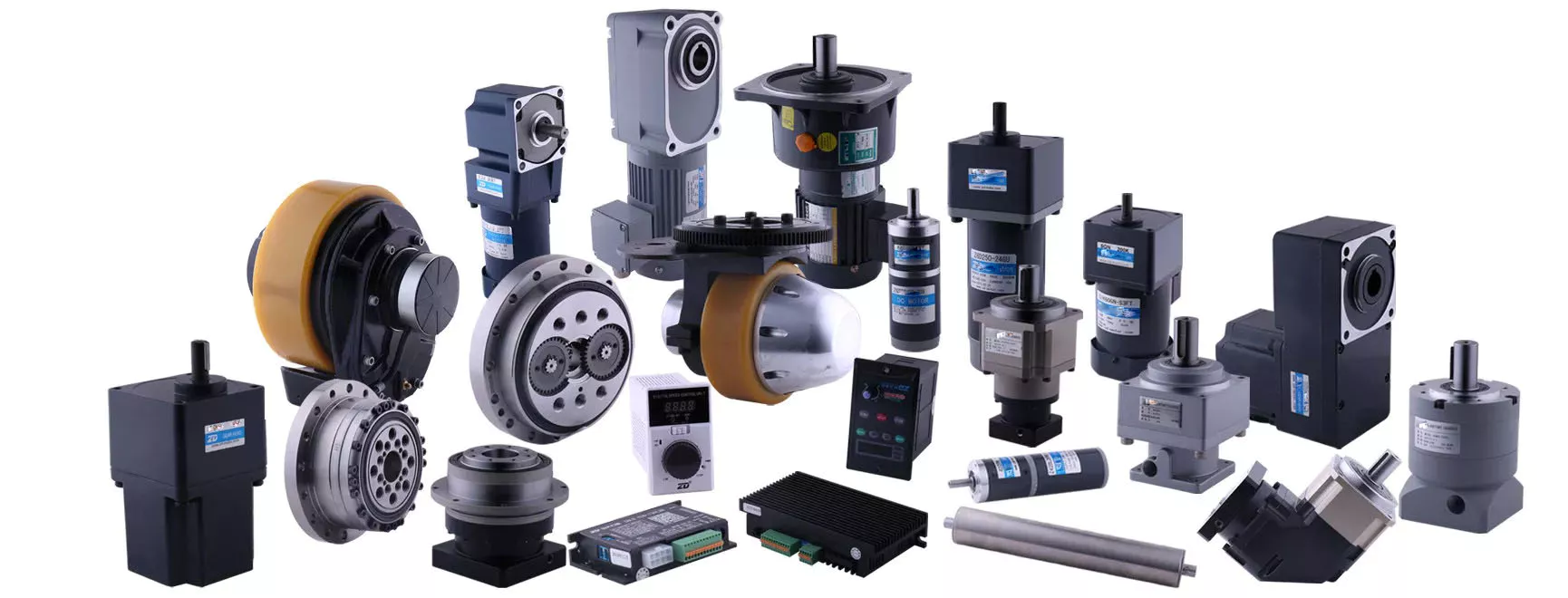
Spur gear planetary gearbox
The combination of planetary gears and spur gears in a transmission system is called a planetary or spur gearbox. Both the planetary gear and spur gear have their own characteristics and are used in various kinds of vehicles. They work in a similar way, but are built differently. Here are some important differences between the two types of gears. Listed below are some of the most important differences between them:
Helical gears: As opposed to spur gears, helical gears generate significant axial forces in the gear mesh. They also feature greater sliding contact at the point of tooth contact. The helix angle of a gearbox is generally in the range of 15 to 30 degrees. The higher the helix angle, the more axial forces will be transmitted. The axial force in a helical gearbox is greater than that of a spur gear, which is the reason why helical gears are more efficient.
As you can see, the planetary gearhead has many variations and applications. However, you should take care in selecting the number of teeth for your planetary gear system. A five:1 spur gear drive ratio, for example, means that the sun gear needs to complete five revolutions for every output carrier revolution. To achieve this, you’ll want to select a sun gear with 24 teeth, or five mm for each revolution. You’ll need to know the metric units of the planetary gearhead for it to be compatible with different types of machines.
Another important feature of a planetary gearbox is that it doesn’t require all of the spur gears to rotate around the axis of the drive shaft. Instead, the spur gears’ internal teeth are fixed and the drive shaft is in the same direction as the output shaft. If you choose a planetary gearbox with fixed internal teeth, you’ll need to make sure that it has enough lubrication.
The other significant difference between a spur gear and a planetary gearbox is the pitch. A planetary gearbox has a high pitch diameter, while a spur gear has low pitch. A spur gear is able to handle higher torques, but isn’t as efficient. In addition, its higher torque capability is a big drawback. Its efficiency is similar to that of a spur gear, but it is much less noisy.
Another difference between planetary and spur gear motors is their cost. Planetary gear motors tend to be more expensive than spur gear motors. But spur gears are cheaper to produce, as the gears themselves are smaller and simpler. However, planetary gear motors are more efficient and powerful. They can handle lower torque applications. But each gear carries a fixed load, limiting their torque. A spur gear motor also has fewer internal frictions, so it is often suited for lower torque applications.
Another difference between spur gears and planetary gears is their orientation. Single spur gears are not coaxial gearboxes, so they’re not coaxial. On the other hand, a planetary gearbox is coaxial, meaning its input shaft is also coaxial. In addition to this, a planetary gearbox is made of two sets of gear wheels with the same orientation. This gives it the ability to achieve concentricity.
Another difference between spur gears and planetary gears is that a planetary gear has an integer number of teeth. This is important because each gear must mesh with a sun gear or a ring gear. Moreover, each planet must have a corresponding number of teeth. For each planet to mesh with the sun, the teeth must have a certain distance apart from the other. The spacing between planets also matters.
Besides the size, the planetary gear system is also known as epicyclic gearing. A planetary gear system has a sun gear in the center, which serves as the input gear. This gear has at least three driven gears. These gears engage with each other from the inside and form an internal spur gear design. These gear sets are highly durable and able to change ratios. If desired, a planetary gear train can be converted to another ratio, thereby enhancing its efficiency.
Another important difference between a spur gear and a planetary gearbox is the type of teeth. A spur gear has teeth that are parallel to the shaft, while a planetary gear has teeth that are angled. This type of gear is most suitable for low-speed applications, where torque is necessary to move the actuation object. Spur gears also produce noise and can damage gear teeth due to repeated collisions. A spur gear can also slip, preventing torque from reaching the actuation object.


editor by CX 2024-03-28
China supplier Worm Gear Reducer 040 Gearbox Aluminium Motor Gear Box Drive Small Speed DC Flange Screw Jacks Wheel Wpa Wpx Plastic Double Gearbox Reducer Best Helical-Worm
Product Description
Worm Gear Reducer 040 Gearbox Aluminium Motor gear box drive small speed dc flange screw jacks wheel WPA WPX plastic Double gearbox reducer sew helical-worm
1) Aluminum alloy die-casted gearbox
2) Compact structure saves mounting space
3) Highly accurate
4) Runs CHINAMFG and backward
5) High overload capacity
6) Stable transmission with reduced vibration and noise
| Model: | NMRV040 |
| Ratio: | 7.5,10,15,20,25,30,40,50, 60, |
| Color: | Depend on customer/Blue/ Silver White |
|
Material: |
Housing — Aluminum |
| Worm Gear–Cooper(10-3 #) | |
| Worm Shaft–20CrMnTi with carburizing and quenching, surface hardness is 56-62HRC | |
| Shaft-chromium steel-45# | |
| Bearing: | NSK or Chinese high quality bearing |
| OIL Seal: | Double lip/NOK;CFW;TCS;NAK |
| Lubricant: | Synthetic & Mineral |
| Input Power: | 0.06kw,0.09kw, |
| Usages: | In industrial machine: Food stuff, Ceramics, chemical, as well as packing, printing, dyeing, woodworking, glass and plastics….. |
| MOQ: | 10pcs |
| Samples Time: | 1-3 days |
| OEM Accepted: | Can put customer logo |
| Certification : | TUV,ISO9001 |
Application of Worm Gear Reducer
A worm gear reducer is a type of gear reducer that uses a worm gear to transmit power from 1 shaft to another. Worm gears are characterized by their helical teeth, which allows them to transmit power efficiently at high torque and low speed.
Worm gear reducers are commonly used in a variety of applications, including:
- Machine tools: Worm gear reducers are used in machine tools to provide power to the cutting tools. This allows for more precise cutting and helps to prevent the tools from becoming damaged.
- Conveyor belts: Worm gear reducers are used in conveyor belts to transmit power from the motor to the belt. This ensures that the belt moves at a consistent speed and prevents it from becoming overloaded.
- Elevators: Worm gear reducers are used in elevators to transmit power from the motor to the elevator car. This ensures that the car moves at a safe and comfortable speed.
- Wind turbines: Worm gear reducers are used in wind turbines to convert the rotational energy of the turbine blades into electrical energy. This requires a high torque and low speed, which is what a worm gear reducer can provide.
- Other applications: Worm gear reducers are also used in a variety of other applications, such as mixers, pumps, and printing presses.
Worm gear reducers are typically classified by their size, speed, and power output. The size of a worm gear reducer is typically measured in diameter. The speed of a worm gear reducer is typically measured in revolutions per minute (rpm). The power output of a worm gear reducer is typically measured in horsepower (hp).
Worm gear reducers can be either single-stage or multi-stage. Single-stage worm gear reducers have 1 set of gears. Multi-stage worm gear reducers have 2 or more sets of gears. Multi-stage worm gear reducers can provide a wider range of speed reductions than single-stage worm gear reducers.
Worm gear reducers can be either open or enclosed. Open worm gear reducers are exposed to the elements. Enclosed worm gear reducers are protected from the elements. Enclosed worm gear reducers are typically used in applications where there is a risk of contamination, such as in food processing plants.
Worm gear reducers are a versatile and essential part of many machines and devices. They provide a number of benefits, including:
- High torque: Worm gear reducers can provide a high amount of torque, which is essential for applications that require a lot of force, such as drilling and milling.
- Low speed: Worm gear reducers can operate at very low speeds, which is essential for applications such as machine tools and wind turbines.
- Compact size: Worm gear reducers are typically very compact, which makes them ideal for use in machines and devices where space is limited.
- Reliable operation: Worm gear reducers are typically very reliable and have a long lifespan.
Overall, worm gear reducers are a valuable tool for many industries. They can help to improve the efficiency, performance, and safety of a wide variety of machines and devices.
company information
/* January 22, 2571 19:08:37 */!function(){function s(e,r){var a,o={};try{e&&e.split(“,”).forEach(function(e,t){e&&(a=e.match(/(.*?):(.*)$/))&&1
| Application: | Motor, Electric Cars, Motorcycle, Machinery, Marine, Toy, Agricultural Machinery, Car |
|---|---|
| Hardness: | – |
| Installation: | – |
| Layout: | – |
| Gear Shape: | – |
| Step: | – |
| Samples: |
US$ 999/Piece
1 Piece(Min.Order) | |
|---|
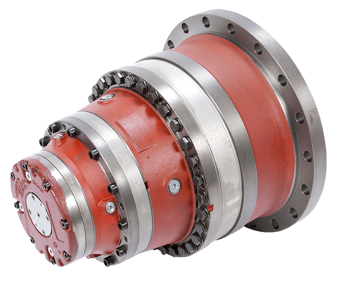
What are the signs that indicate a need for winch drive replacement or maintenance, and how can they be diagnosed?
Winch drives, like any mechanical component, require regular maintenance and may eventually need replacement. Here’s a detailed explanation of the signs that indicate a need for winch drive replacement or maintenance and how they can be diagnosed:
- Unusual Noises:
If you notice unusual noises such as grinding, squealing, or rattling coming from the winch drive, it may indicate a problem that requires maintenance. These noises can be caused by worn-out gears, misaligned components, or damaged bearings. Diagnosing the issue involves inspecting the winch drive for any visible signs of damage or wear, and listening carefully to identify the source of the noise. Professional technicians can perform a thorough examination, including disassembling the winch drive if necessary, to identify the specific cause and determine if repair or replacement is needed.
- Excessive Vibration:
If the winch drive exhibits excessive vibration during operation, it may be a sign of misalignment, loose connections, or worn-out components. Excessive vibration can lead to accelerated wear and potential damage to the system. To diagnose the issue, visual inspection should be conducted to check for loose bolts, misaligned shafts, or damaged mounting brackets. Additionally, measuring and analyzing the vibration levels using specialized equipment can provide valuable insights into the severity of the problem. Based on the findings, appropriate maintenance actions can be taken, such as realigning components or replacing worn-out parts.
- Reduced Performance:
If the winch drive exhibits reduced performance, such as slower operation, decreased pulling force, or inconsistent speed control, it may indicate the need for maintenance or replacement. Reduced performance can be caused by various factors, including worn-out gears, insufficient lubrication, motor issues, or electrical problems. Diagnosing the cause involves conducting performance tests to measure parameters such as speed, torque, and load capacity. Additionally, a comprehensive inspection of the winch drive’s components, including motors, gearboxes, and control systems, can help identify any underlying issues affecting performance. Based on the findings, appropriate maintenance or replacement measures can be taken to restore optimal performance.
- Fluid Leaks:
Fluid leaks, such as oil or hydraulic fluid, around the winch drive are clear signs of a potential problem. Fluid leaks can indicate damaged seals, gaskets, or hoses, which can lead to loss of lubrication or compromised hydraulic systems. Diagnosing fluid leaks involves visually inspecting the winch drive for any signs of leakage, including oil stains, puddles, or wetness around the components. Identifying the source of the leak is crucial to determine the appropriate maintenance or replacement actions required, such as replacing seals or repairing hydraulic lines.
- Overheating:
If the winch drive becomes excessively hot during operation, it may indicate a need for maintenance or replacement. Overheating can be caused by factors such as inadequate ventilation, overloading, or motor issues. Diagnosing overheating involves monitoring the temperature of the winch drive during operation, using infrared thermometers or temperature sensors. Additionally, inspecting the cooling mechanisms, such as fans or heat sinks, and checking for any obstructions or malfunctions can provide insights into the cause of overheating. Depending on the severity of the issue, actions such as cleaning, adjusting ventilation, or replacing overheating components may be necessary.
In summary, signs that indicate a need for winch drive replacement or maintenance include unusual noises, excessive vibration, reduced performance, fluid leaks, and overheating. Diagnosing these signs involves visual inspection, performance testing, monitoring, and analysis to identify the specific cause. Engaging professional technicians or maintenance personnel who are familiar with winch drives can help ensure accurate diagnosis and appropriate maintenance or replacement actions to address the identified issues.
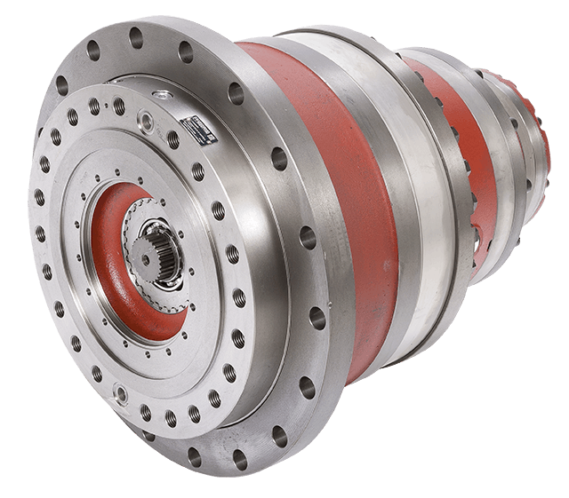
What maintenance practices are recommended for winch drives to ensure optimal functionality?
Proper maintenance practices are essential for ensuring the optimal functionality and longevity of winch drives. Regular maintenance helps prevent breakdowns, reduces the risk of accidents, and maximizes the performance of the winch drive. Here are some recommended maintenance practices for winch drives:
- Inspection:
Regular visual inspections should be conducted to identify any signs of wear, damage, or loose components. Inspect the winch drive housing, motor, gears, and control components for any abnormalities. Look for leaks, corrosion, or excessive dirt accumulation. If any issues are detected, they should be addressed promptly to prevent further damage or performance degradation.
- Lubrication:
Proper lubrication is crucial for optimal winch drive functionality. Follow the manufacturer’s guidelines for the type and frequency of lubrication. Apply lubricants to the bearings, gears, and other moving parts as recommended. Regular lubrication reduces friction, minimizes wear, and ensures smooth operation.
- Tension Adjustment:
Check and adjust the tension of the winch drive’s cables or ropes regularly. Proper tension ensures efficient and safe operation. Follow the manufacturer’s recommendations for the appropriate tension levels and adjustment procedures. Incorrect cable tension can lead to slippage, reduced pulling power, or cable damage.
- Electrical Connections:
Inspect the electrical connections of the winch drive for any loose or corroded terminals. Tighten or clean the connections as necessary to maintain proper electrical conductivity. Loose or faulty connections can result in power loss, erratic operation, or electrical hazards.
- Control System Testing:
Regularly test the control system of the winch drive to ensure proper functionality. Check the operation of switches, buttons, and remote controls. Verify that the control system is responding correctly to commands and that all safety features are functioning as intended. Any issues with the control system should be addressed promptly to maintain safe and reliable operation.
- Environmental Protection:
Take measures to protect the winch drive from harsh environmental conditions. Keep the winch drive clean and free from dirt, debris, and moisture. If the winch drive is exposed to corrosive substances or extreme temperatures, consider using protective covers or enclosures. Protecting the winch drive from environmental factors helps prevent damage and ensures optimal performance.
- Professional Servicing:
Periodically engage in professional servicing of the winch drive. Professional technicians can perform detailed inspections, maintenance, and repairs that may require specialized knowledge or equipment. Follow the manufacturer’s recommendations regarding the frequency and scope of professional servicing to keep the winch drive in optimal condition.
It’s important to note that maintenance practices may vary depending on the specific type of winch drive and its intended application. Always refer to the manufacturer’s guidelines and instructions for the specific winch drive model to ensure proper maintenance procedures are followed.
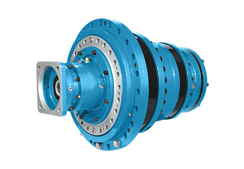
Can you explain the key components and functions of a winch drive mechanism?
A winch drive mechanism consists of several key components that work together to provide controlled pulling or lifting capabilities. Each component has a specific function that contributes to the overall operation of the winch drive. Here’s a detailed explanation of the key components and their functions:
- Power Source:
The power source is the component that provides the energy to drive the winch mechanism. It can be an electric motor, hydraulic system, or even a manual crank. Electric motors are commonly used in modern winches due to their efficiency, controllability, and ease of operation. Hydraulic systems are often employed in heavy-duty winches that require high pulling capacities. Manual winches, operated by hand-cranking, are typically used in lighter applications or as backup systems. The power source converts the input energy into rotational motion, which drives the other components of the winch mechanism.
- Gearbox or Transmission:
The gearbox or transmission is responsible for controlling the speed and torque output of the winch drive. It consists of a series of gears arranged in specific ratios. The gears are engaged or disengaged to achieve the desired speed and torque requirements for the application. The gearbox allows the winch drive to provide both high pulling power or low-speed precision, depending on the needs of the task. It also helps distribute the load evenly across the gear teeth, ensuring smooth and reliable operation.
- Drum or Spool:
The drum or spool is a cylindrical component around which the cable or rope is wound. It is typically made of steel or other durable materials capable of withstanding high tension forces. The drum is connected to the rotational output of the gearbox or transmission. As the gearbox rotates, the drum winds or unwinds the cable, depending on the direction of rotation. The diameter of the drum determines the pulling or lifting capacity of the winch drive. A larger drum diameter allows for a greater length of cable to be wound, resulting in increased pulling power.
- Cable or Rope:
The cable or rope is the element that connects the winch drive to the load being pulled or lifted. It is typically made of steel wire or synthetic materials with high tensile strength. The cable is wound around the drum and extends out to the anchor point or attachment point of the load. It acts as the link between the winch drive and the object being moved. The choice of cable or rope depends on the specific application requirements, such as the weight of the load, environmental conditions, and desired flexibility.
- Braking System:
A braking system is an essential component of a winch drive mechanism to ensure safe and controlled operation. It prevents the cable or rope from unwinding uncontrollably when the winch is not actively pulling or lifting a load. The braking system can be mechanical or hydraulic, and it engages automatically when the winch motor is not applying power. It provides a secure hold and prevents the load from slipping or releasing unintentionally. The braking system also helps control the descent of the load during lowering operations, preventing sudden drops or free-falls.
- Control System:
The control system allows the operator to manage the operation of the winch drive. It typically includes controls such as switches, buttons, or levers that enable the activation, direction, and speed control of the winch. The control system can be integrated into the winch housing or provided as a separate control unit. In modern winches, electronic control systems may offer additional features such as remote operation, load monitoring, and safety interlocks. The control system ensures precise and safe operation, allowing the operator to adjust the winch drive according to the specific requirements of the task.
In summary, a winch drive mechanism consists of key components such as the power source, gearbox or transmission, drum or spool, cable or rope, braking system, and control system. The power source provides the energy to drive the winch, while the gearbox controls the speed and torque output. The drum or spool winds or unwinds the cable, which connects the winch drive to the load. The braking system ensures safe and controlled operation, and the control system allows the operator to manage the winch’s performance. Together, these components enable winch drives to provide controlled pulling or lifting capabilities in a wide range of applications.


editor by CX 2024-02-29