Product Description
China Low Price DC 12v Worm Geared Motor Reducer for Sale
Model:D76R(72)-24v45w-40rpm
| Type | electric dc gear motor | ||
| Motor Diameter | 76mm | ||
| Voltage | 12v 24v 36v 42v 48v | ||
| Power | ≤150W | ||
| Torque | ≤23N.M | ||
| Speed | ≤300RPM | ||
| Gear of ratio | 60:1 20:1 47:2 | ||
| Gear Modulus | 60:1 20:1 M=1 | ||
| Material of gear | Plastic /brass | ||
| OEM/ODM Service | Accept | ||
| Usage | Hydraulic pump,electric forklift truck,vacuum cleaner , sweep,scrubber ,welding machine ,electrical household, vending macine, auto garage door opener,other electric tools . | ||
HangZhou CHINAMFG Science & Technology Co.,Ltd is a subsidiary of HangZhou CHINAMFG Motor Co.,Ltd.The factory is located in Xihu (West Lake) Dis.,HangZhou,we can design and manufacture of motors according to all our customers’ demands so far,we can manufacture about 60,000 motors per month.
Our main market:
Europe,America and Asia,including United Kingdom, Germany, Italy, France, Sweden, United State,India,Korea and so on.
Company Advantages:
1. Big production capacity, fast delivery.
2. Strict QC inspecting rules: all products must be 100% inspected before delivery.
3. OEM/ODM services are available
4. 24 hours online service.
5. Prompt quotation for your inquiry
6. Quality,reliability and long product life.
7. Professional manufacturer offers competitive price.
8. Diversified rich experienced skilled workers.
More Applications:
Car simulator ,garage door opener ,gate operator, packing barrier,wheelchair ,electric vehicle ,water pump ,floor polisher,truck lift,stair lift,hospital bed ,hydraulic pump electric forklift.
RFQ:
Q: Are you trading company or manufacturer ?
A: We are Integration of industry and trade, with over 20 years experience in DC worm gear motor. Our company have accumulated skilled production line, complete management and powerful research support, which could match all of the customers’ requirements and make them satisfaction.
Q: What is your main product?
–DC Motor: Gear motor, Square motor, Stepped motor, and Micro motor
-Welding equipment: Wire feeder, Welding rod, Welding Torch, Earth clamp, Electrode holder, and Rectifier
Q: What if I don’t know which DC motor I need?
A: Don’t worry, Send as much information as you can, our team will help you find the right 1 you are looking for.
Q: What is your terms of payment ?
A: Payment=1000USD, 30% T/T in advance ,balance before shippment.
If you have another question, pls feel free to contact us as below:
Q: How to delivery:
A: By sea – Buyer appoint forwarder, or our sales team find suitable forwarder for buyers.
By air – Buyer offer collect express account, or our sales team find suitable express for buyers. (Mostly for sample)
Others – Actually,samples send by DHL,UPS, TNT and Fedex etc. We arrange to delivery goods to some place from China appointed by buyers.
Q: How long is your delivery time?
A: Generally it is 5-10 days if the goods are in stock. or it is 15-20 days if the goods are not in stock, it is according to quantity.
/* March 10, 2571 17:59:20 */!function(){function s(e,r){var a,o={};try{e&&e.split(“,”).forEach(function(e,t){e&&(a=e.match(/(.*?):(.*)$/))&&1
| Application: | Universal, Industrial, Household Appliances, Power Tools, Industrial Machine |
|---|---|
| Operating Speed: | Low Speed |
| Excitation Mode: | Permanent Magnent |
| Samples: |
US$ 150/Piece
1 Piece(Min.Order) | Order Sample Sample fee will be returned when order reaches 200
|
|---|
| Customization: |
Available
|
|
|---|
.shipping-cost-tm .tm-status-off{background: none;padding:0;color: #1470cc}
|
Shipping Cost:
Estimated freight per unit. |
about shipping cost and estimated delivery time. |
|---|
| Payment Method: |
|
|---|---|
|
Initial Payment Full Payment |
| Currency: | US$ |
|---|
| Return&refunds: | You can apply for a refund up to 30 days after receipt of the products. |
|---|
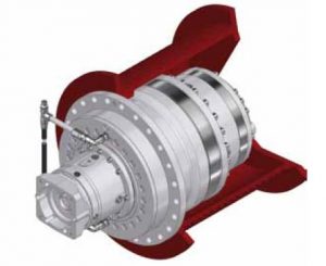
How do electronic or computer-controlled components integrate with winch drives in modern applications?
In modern applications, electronic or computer-controlled components play a crucial role in enhancing the functionality, precision, and safety of winch drives. These components integrate with winch drives to provide advanced control, monitoring, and automation capabilities. Here’s a detailed explanation of how electronic or computer-controlled components integrate with winch drives in modern applications:
- Control Systems:
Electronic or computer-controlled components are used to create sophisticated control systems for winch drives. These control systems allow operators to precisely control the speed, direction, and position of the winch drive. By integrating sensors, actuators, and feedback mechanisms, the control system can monitor the operating conditions and adjust parameters in real-time to optimize performance. Control systems may include programmable logic controllers (PLCs), microcontrollers, or dedicated electronic control units (ECUs) that communicate with the winch drive to execute commands and maintain desired operating parameters.
- Human-Machine Interfaces (HMIs):
Electronic components enable the integration of intuitive and user-friendly Human-Machine Interfaces (HMIs) with winch drives. HMIs provide a visual interface for operators to interact with the winch drive system. Touchscreen displays, buttons, switches, and graphical user interfaces (GUIs) allow operators to input commands, monitor system status, and access diagnostic information. HMIs also facilitate the adjustment of control parameters, alarm settings, and operational modes. The integration of HMIs enhances operator control and simplifies the operation of winch drives in modern applications.
- Sensors and Feedback Systems:
Electronic sensors are employed to gather real-time data about various parameters related to the winch drive and the operating environment. These sensors can measure variables such as load weight, cable tension, speed, temperature, and motor current. The collected data is then fed back to the control system, allowing it to make informed decisions and adjustments. For example, if the load exceeds a predefined limit, the control system can send a signal to stop the winch drive or activate an alarm. Sensors and feedback systems ensure accurate monitoring of operating conditions and enable proactive control and safety measures.
- Communication Protocols:
Electronic or computer-controlled components facilitate communication between winch drives and other devices or systems. Modern winch drives often support various communication protocols, such as Ethernet, CAN bus, Modbus, or Profibus, which enable seamless integration with higher-level control systems, supervisory systems, or industrial networks. This integration allows for centralized control, remote monitoring, and data exchange between the winch drive and other components or systems, enhancing coordination and automation in complex applications.
- Automation and Programmability:
Electronic or computer-controlled components enable advanced automation and programmability features in winch drives. With the integration of programmable logic controllers (PLCs) or microcontrollers, winch drives can execute pre-programmed sequences of operations, follow specific load profiles, or respond to external commands and triggers. Automation reduces manual intervention, improves efficiency, and enables synchronized operation with other equipment or systems. Programmability allows customization and adaptation of winch drive behavior to meet specific application requirements.
- Diagnostics and Condition Monitoring:
Electronic components enable comprehensive diagnostics and condition monitoring of winch drives. Built-in sensors, data logging capabilities, and advanced algorithms can monitor the health, performance, and operating parameters of the winch drive in real-time. This information can be used for predictive maintenance, early fault detection, and performance optimization. Additionally, remote access and network connectivity enable remote monitoring and troubleshooting, reducing downtime and improving maintenance efficiency.
In summary, electronic or computer-controlled components integrate with winch drives in modern applications to provide advanced control, monitoring, automation, and safety features. These components enable precise control, user-friendly interfaces, data-driven decision-making, communication with other systems, automation, and diagnostics. The integration of electronic components enhances the functionality, efficiency, and reliability of winch drives in a wide range of applications.
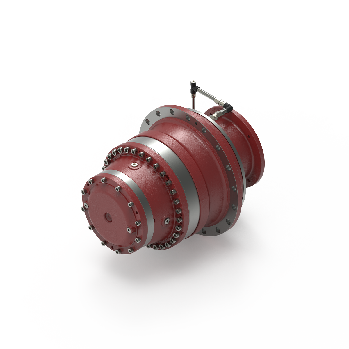
What safety considerations should be taken into account when using winch drives?
Using winch drives involves certain safety considerations to ensure the well-being of operators, prevent accidents, and protect the equipment and the load being lifted. Here’s a detailed explanation of the safety considerations that should be taken into account when using winch drives:
- Operator Training:
Proper training is essential for operators who will be using winch drives. They should receive comprehensive training on the safe operation of winch drives, including understanding the controls, procedures, safety features, and potential hazards. Training should cover load calculations, safe working loads, and the importance of following safety guidelines and manufacturer’s instructions.
- Equipment Inspection:
Prior to each use, winch drives should be thoroughly inspected to ensure they are in proper working condition. This includes checking for any signs of damage, wear, or corrosion. The cables or ropes should be inspected for fraying, kinks, or other defects. Any damaged or malfunctioning components should be repaired or replaced before operating the winch drive.
- Load Capacity:
It is crucial to adhere to the specified load capacity of the winch drive. Exceeding the maximum load capacity can lead to equipment failure, accidents, and injuries. Operators should accurately determine the weight of the load to be lifted and ensure it falls within the winch drive’s rated capacity. If the load exceeds the capacity, alternative lifting methods or equipment should be used.
- Secure Anchoring:
Winch drives should be securely anchored to a stable and appropriate mounting point. This ensures that the winch drive remains stable during operation and prevents unintended movement. The anchoring point should be capable of withstanding the forces generated during lifting or pulling operations. Proper anchoring minimizes the risk of equipment tipping over or shifting unexpectedly.
- Personal Protective Equipment (PPE):
Operators should wear appropriate personal protective equipment (PPE) when using winch drives. This may include safety helmets, gloves, eye protection, and high-visibility clothing. PPE helps protect operators from potential hazards such as falling objects, flying debris, or contact with moving parts. The specific PPE requirements should be determined based on the nature of the lifting operation and any applicable safety regulations.
- Safe Operating Distance:
Operators and other personnel should maintain a safe distance from the winch drive during operation. This prevents accidental contact with moving parts or the load being lifted. Clear warning signs or barriers should be used to define the restricted area around the winch drive. Operators should never place themselves or others in the potential path of the load or in a position where they could be struck by the load in case of a failure or slippage.
- Emergency Stop and Controls:
Winch drives should be equipped with emergency stop mechanisms or controls that allow operators to quickly halt the operation in case of an emergency. All operators should be familiar with the location and operation of the emergency stop controls. Regular testing and maintenance of these controls are essential to ensure their effectiveness in emergency situations.
- Proper Rigging and Rigging Techniques:
Correct rigging techniques should be followed when attaching the load to the winch drive. This includes using appropriate slings, hooks, or attachments and ensuring they are properly secured. Improper rigging can lead to load instability, shifting, or falling, posing a significant safety risk. Operators should be trained in proper rigging techniques and inspect the rigging components for wear or damage before each use.
- Regular Maintenance:
Winch drives should undergo regular maintenance as recommended by the manufacturer. This includes lubrication, inspection of cables or ropes, checking for loose bolts or connections, and verifying the functionality of safety features. Regular maintenance helps identify and address potential issues before they lead to equipment failure or accidents.
By considering these safety measures, operators can ensure the safe and effective use of winch drives, minimizing the risk of accidents, injuries, or equipment damage. It is crucial to prioritize safety at all times and to comply with applicable safety regulations and guidelines.
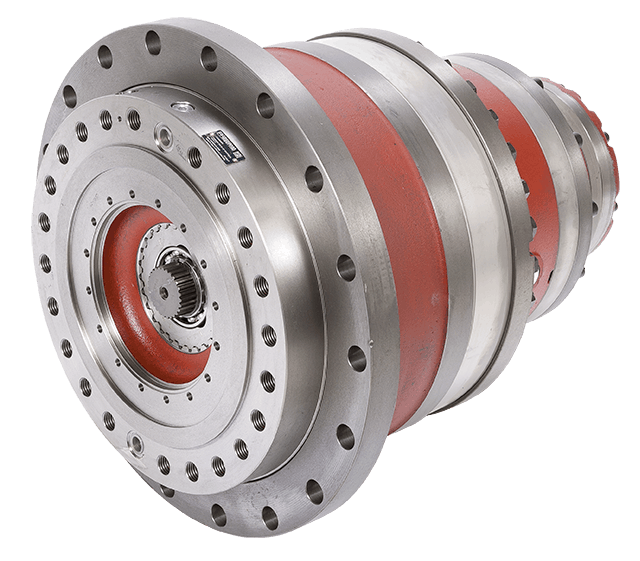
Can you describe the various types and configurations of winch drives available in the market?
There are several types and configurations of winch drives available in the market, each designed to suit specific applications and requirements. Here’s a detailed description of the various types and configurations of winch drives:
- Electric Winch Drives:
Electric winch drives are powered by electric motors and are widely used in various industries. They are available in different load capacities and configurations. Electric winches are known for their ease of use, precise control, and relatively low maintenance requirements. They can be mounted on vehicles, equipment, or structures and are commonly used in applications such as vehicle recovery, marine operations, construction sites, and material handling.
- Hydraulic Winch Drives:
Hydraulic winch drives are powered by hydraulic systems and offer high pulling power for heavy-duty applications. They are commonly used in industries such as construction, oil and gas, and marine operations. Hydraulic winch drives are known for their robustness, durability, and ability to handle extreme loads. They are often mounted on large vehicles, cranes, or offshore platforms. Hydraulic winch drives require hydraulic power sources, such as hydraulic pumps, and are suitable for applications that require continuous and sustained pulling power.
- Pneumatic Winch Drives:
Pneumatic winch drives utilize compressed air as the power source. They are mainly used in hazardous or explosive environments where electric or hydraulic power sources are not suitable. Pneumatic winch drives are commonly found in industries such as mining, oil refineries, and chemical plants. They offer a high level of safety due to the absence of electrical components and are capable of handling heavy loads in challenging environments.
- Planetary Winch Drives:
Planetary winch drives are a popular type of winch drive known for their compact size, high efficiency, and high torque output. They consist of a central sun gear, multiple planetary gears, and an outer ring gear. The planetary gear system allows for high torque multiplication while maintaining a compact design. Planetary winch drives are commonly used in off-road vehicles, ATV winches, and small to medium-sized industrial applications.
- Worm Gear Winch Drives:
Worm gear winch drives utilize a worm gear mechanism to achieve high gear reduction ratios. They offer excellent load holding capabilities and are commonly used in applications where precise load control and safety are paramount. Worm gear winch drives are popular in industries such as construction, theater rigging, and material handling. They are known for their self-locking feature, which prevents backdriving and provides secure load holding.
- Capstan Winch Drives:
Capstan winch drives are designed with a rotating drum or capstan instead of a traditional spool. They are commonly used in applications that require constant tension or controlled pulling speeds, such as in marine settings for mooring operations or on fishing vessels. Capstan winch drives offer efficient and continuous pulling power and are suitable for handling ropes, cables, or lines with minimal slippage.
- Wire Rope Winch Drives:
Wire rope winch drives are specifically designed to handle wire ropes as the lifting or pulling medium. They are equipped with drums that accommodate wire ropes of different diameters and lengths. Wire rope winch drives are commonly used in industries such as construction, mining, and offshore operations. They offer high load capacities and are suitable for heavy-duty applications that require strength, durability, and resistance to abrasion.
These are some of the various types and configurations of winch drives available in the market. Each type has its own advantages and is designed to cater to specific applications and industry requirements. When selecting a winch drive, it’s important to consider factors such as load capacity, power source, control mechanisms, and environmental conditions to ensure optimal performance and efficiency.


editor by CX 2024-01-16
China China OEM 36mm gear box 12v 18v 24v 2800rpm 10rpm low rpm big torque 5nm 60kgf 15 watt electric dc planetary gear reducer motor with Great quality
Guarantee: 3months-1year
Design Amount: TJX36RO
Utilization: Home Appliance, Cosmetic instrument, Sensible Property, Industrial robotic
Variety: Gear MOTOR
Torque: ten N.m
Development: Long lasting Magnet
Commutation: Brush
Protect Function: Drip-evidence
Velocity(RPM): 5~15pcs.* Our guarantee time period is 1 yr.* We have 5 R&D engineers can supply you specialist remedies.* We have a competitive price in Chinese market, or even in the total planet.* ten to 40 days quickly shipping time base on diverse quantities.* We have CE and ROHS certifications.* Our customer support staff will reply to you in twelve hours. Firm Historical past Factory Real Landscape Solution Certificates Consumers Feedback OEM & ODM CAD style: All components of dc gear motor are designed and drawn by our engineers. We use CAXA, NGWN to design and style different gears for our new merchandise. Solidworks is a skilled 3D modeling software, we will design and style motor areas and using 3D model for assembly verification. We have a demanding merchandise advancement process, the standard merchandise improvement cycle in 40-sixty times Packing and shipping 1. All buy schedules are managed separately by every single salesman 2. All resources go via rigid good quality inspection 3. All concluded products will be shipped out after passing inspection 4. All products are packed in foam cartons: The sample delivery time of every expresses are as follows(for example to the US): * DHL 7~12 perform times * FedEx 6~9 function times * TNT 7~12 perform days * UPS 8~eleven work times * EMS ten~18 function days The supply date of bulk items wants distinct negotiation. If the sample is delayed, we will advise you in progress and confirm the new delivery time. FAQ Q: Are you investing business or producer ?A: We are manufacturing unit.Q: How to get?A: Send out us inquiry → Obtain our quotation → Negotiate specifics → Confirm the sample → Indication deal/deposit → Mass manufacturing → Cargo all set → Balance/shipping and delivery → AB60 helical precision Servo Planetary gearbox ratio 3,4,5,6,7,8,10 Even more cooperationQ: How about Sample purchase?A: Sample is available for you. remember to contact us for specifics. As soon as we charge you sample price, please really feel simple, it would be refund when you area formal get.Q: Which shipping and delivery way is accessible?A: DHL, UPS, FedEx, TNT, EMS, China Put up,Sea are obtainable.The other shipping and delivery approaches are also accessible, please speak to us if you require ship by the other delivery way. Q: How extended is the deliver[Producing] and shipping?A: Produce time relies upon on the amount you get. usually it normally takes 7-15 functioning times.Q: My bundle has missing items. What can I do?A: Please speak to our help team and we will confirm your buy with the deal contents.We apologize for any inconveniences. Q: How to verify the payment?A: We take payment by T/T, PayPal, the other payment techniques also could be recognized,Make sure you speak to us just before you shell out by the other payment ways. Also thirty-50% deposit is accessible, the equilibrium money need to be paid just before delivery.
| >>>>>>>>>>>>> Benoy precision computerized planetary gearbox gear reducer for business >Back to Homepage | ||||||||
Planetary Gearbox
This article will explore the design and applications of a planetary gearbox. The reduction ratio of a planetary gearbox is dependent on the number of teeth in the gears. The ratios of planetary gearboxes are usually lower than those of conventional mechanical transmissions, which are mainly used to drive engines and generators. They are often the best choice for heavy-duty applications. The following are some of the advantages of planetary gearboxes.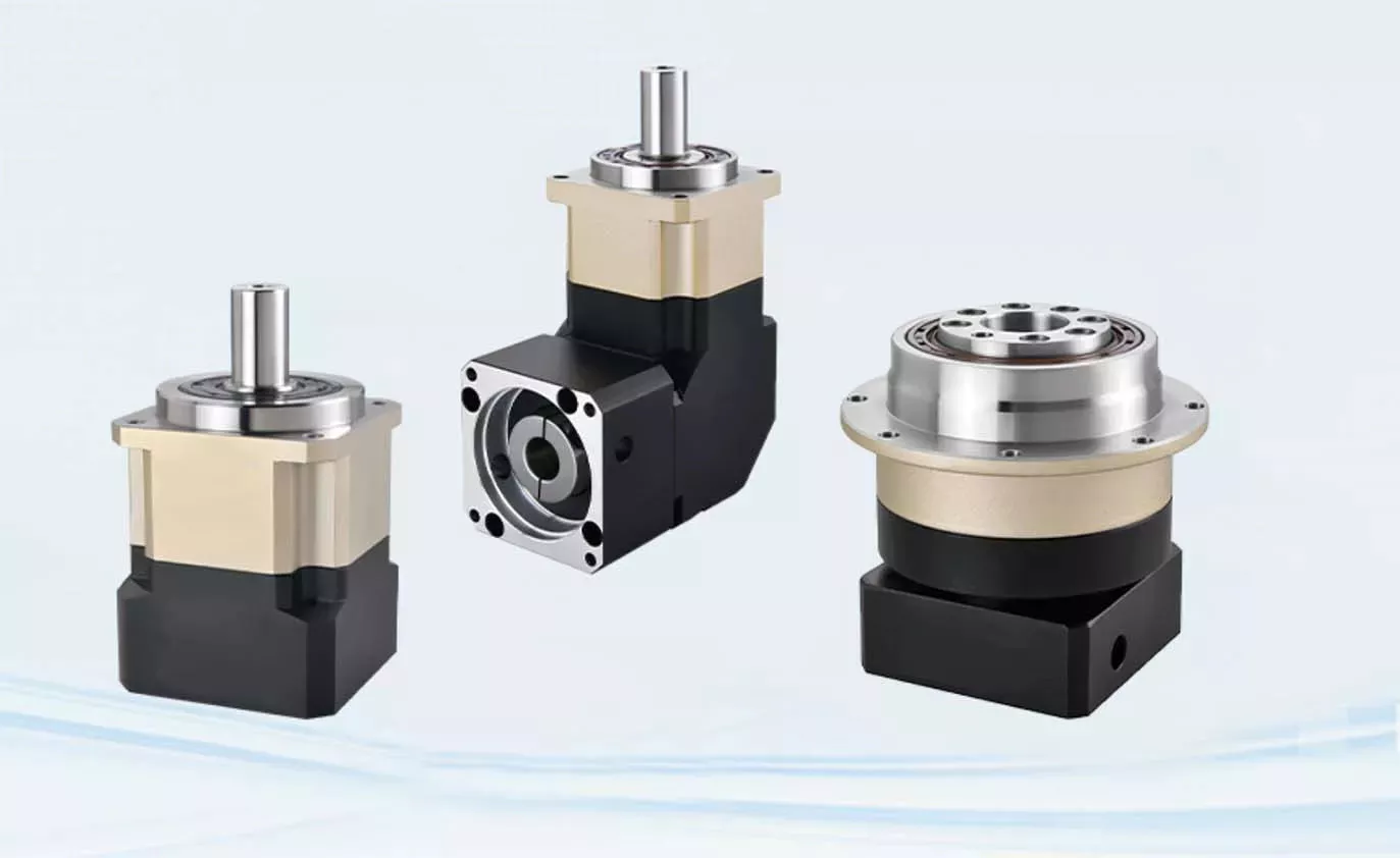
planetary gearboxes
Planetary gearboxes work on a similar principle to solar systems. They rotate around a center gear called the sun gear, and two or more outer gears, called planet gears, are connected by a carrier. These gears then drive an output shaft. The arrangement of planet gears is similar to that of the Milky Way’s ring of planets. This arrangement produces the best torque density and stiffness for a gearbox.
As a compact alternative to normal pinion-and-gear reducers, planetary gearing offers many advantages. These characteristics make planetary gearing ideal for a variety of applications, including compactness and low weight. The efficiency of planetary gearing is enhanced by the fact that ninety percent of the input energy is transferred to the output. The gearboxes also have low noise and high torque density. Additionally, their design offers better load distribution, which contributes to a longer service life.
Planetary gears require lubrication. Because they have a smaller footprint than conventional gears, they dissipate heat well. In fact, lubrication can even lower vibration and noise. It’s also important to keep the gears properly lubricated to prevent the wear and tear that comes with use. The lubrication in planetary gears also helps keep them operating properly and reduces wear and tear on the gears.
A planetary gearbox uses multiple planetary parts to achieve the reduction goal. Each gear has an output shaft and a sun gear located in the center. The ring gear is fixed to the machine, while the sun gear is attached to a clamping system. The outer gears are connected to the carrier, and each planetary gear is held together by rings. This arrangement allows the planetary gear to be symmetrical with respect to the input shaft.
The gear ratio of a planetary gearbox is defined by the sun gear’s number of teeth. As the sun gear gets smaller, the ratio of the gear will increase. The ratio range of planetary gears ranges from 3:1 to ten to one. Eventually, however, the sun gear becomes too small, and the torque will fall significantly. The higher the ratio, the less torque the gears can transmit. So, planetary gears are often referred to as “planetary” gears.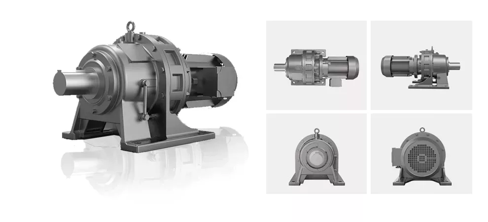
Their design
The basic design of a Planetary Gearbox is quite simple. It consists of three interconnecting links, each of which has its own torque. The ring gear is fixed to the frame 0 at O, and the other two are fixed to each other at A and B. The ring gear, meanwhile, is attached to the planet arm 3 at O. All three parts are connected by joints. A free-body diagram is shown in Figure 9.
During the development process, the design team will divide the power to each individual planet into its respective power paths. This distribution will be based on the meshing condition of all gears in the system. Then, the design team will proceed to determine the loads on individual gear meshes. Using this method, it is possible to determine the loads on individual gear meshes and the shape of ring gear housing.
Planetary Gearboxes are made of three gear types. The sun gear is the center, which is connected to the other two gears by an internal tooth ring gear. The planet pinions are arranged in a carrier assembly that sets their spacing. The carrier also incorporates an output shaft. The three components in a Planetary Gearbox mesh with each other, and they rotate together as one. Depending on the application, they may rotate at different speeds or at different times.
The planetary gearbox’s design is unique. In a planetary gearbox, the input gear rotates around the central gear, while the outer gears are arranged around the sun gear. In addition, the ring gear holds the structure together. A carrier connects the outer gears to the output shaft. Ultimately, this gear system transmits high torque. This type of gearbox is ideal for high-speed operations.
The basic design of a Planetary Gearbox consists of multiple contacts that must mesh with each other. A single planet has an integer number of teeth, while the ring has a non-integer number. The teeth of the planets must mesh with each other, as well as the sun. The tooth counts, as well as the planet spacing, play a role in the design. A planetary gearbox must have an integer number of teeth to function properly.
Applications
In addition to the above-mentioned applications, planetary gearing is also used in machine tools, plastic machinery, derrick and dock cranes, and material handling equipments. Further, its application is found in dredging equipment, road-making machinery, sugar crystallizers, and mill drives. While its versatility and efficiency makes it a desirable choice for many industries, its complicated structure and construction make it a complex component.
Among the many benefits of using a planetary gearbox, the ability to transmit greater torque into a controlled space makes it a popular choice for many industries. Moreover, adding additional planet gears increases the torque density. This makes planetary gears suitable for applications requiring high torque. They are also used in electric screwdrivers and turbine engines. However, they are not used in everything. Some of the more common applications are discussed below:
One of the most important features of planetary gearboxes is their compact footprint. They are able to transmit torque while at the same time reducing noise and vibration. In addition to this, they are able to achieve a high speed without sacrificing high-quality performance. The compact footprint of these gears also allows them to be used in high-speed applications. In some cases, a planetary gearbox has sliding sections. Some of these sections are lubricated with oil, while others may require a synthetic gel. Despite these unique features, planetary gears have become common in many industries.
Planetary gears are composed of three components. The sun gear is the input gear, whereas the planet gears are the output gears. They are connected by a carrier. The carrier connects the input shaft with the output shaft. A planetary gearbox can be designed for various requirements, and the type you use will depend on the needs of your application. Its design and performance must meet your application’s needs.
The ratios of planetary gears vary depending on the number of planets. The smaller the sun gear, the greater the ratio. When planetary stages are used alone, the ratio range is 3:1 to 10:1. Higher ratios can be obtained by connecting several planetary stages together in the same ring gear. This method is known as a multi-stage gearbox. However, it can only be used in large gearboxes.
Maintenance
The main component of a planetary gearbox is the planetary gear. It requires regular maintenance and cleaning to remain in top shape. Demand for a longer life span protects all other components of the gearbox. This article will discuss the maintenance and cleaning procedures for planetary gears. After reading this article, you should know how to maintain your planetary gearbox properly. Hopefully, you can enjoy a longer life with your gearbox.
Firstly, it is important to know how to properly lubricate a planetary gearbox. The lubricant is essential as gears that operate at high speeds are subject to high levels of heat and friction. The housing of the planetary gearbox should be constructed to allow the heat to dissipate. The recommended oil is synthetic, and it should be filled between 30 and 50 percent. The lubricant should be changed at least every six months or as needed.
While it may seem unnecessary to replace a planetary gearbox, regular servicing will help it last a long time. A regular inspection will identify a problem and the appropriate repairs are needed. Once the planetary gearbox is full, it will plug with gear oil. To avoid this problem, consider getting the unit repaired instead of replacing the gearbox. This can save you a lot of money over a new planetary gearbox.
Proper lubrication is essential for a long life of your planetary gearbox. Oil change frequency should be based on oil temperature and operating speed. Oil at higher temperatures should be changed more frequently because it loses its molecular structure and cannot form a protective film. After this, oil filter maintenance should be performed every few months. Lastly, the gearbox oil needs to be checked regularly and replaced when necessary.


editor by czh 2023-02-13