Product Description
Product Description
WP series worm gear reducer
1. Stable transmission.
2. High torque, Strong bearing capacity.
3. Large transmission ratio and wide power.
4. Good redistance to wearing,with high precision in dimensions, lower noise.
| WP series worm gear reducer | |
| WPA/WPS/WPO/WPX/WPZ/WPW/WPZ | |
| Model | 040~250 |
| Ratio | Single stage: 5~60 |
| double stage: 200~900 | |
| Input Power | Single stage: 0.12~33.20kW |
| double stage:0.12~11.71kW | |
| Output Torque | Single stage: 6~6050N.m |
| double stage: 63~6050 N.m | |
|
Material: |
Housing: Die-Cast Iron cast |
|
Worm Gear-Copper-10-3# |
|
|
Worm-20CrMn Ti with carburizing and quenching, surface harness is 56-62HRC |
|
|
Shaft-chromium steel-45# |
|
| Lubricate oil | Synthetic oil |
| Paint brand and color | Blue/Silver/Grey or on request |
| Warranty | 12 months |
Detailed Photos
Single speed reducer
Double speed reducer
Catalogue
Workshop
Lots of worm gears and worm shafts in stock.
Assembling line
Cleaning+Painting+ drying after assembling
Final finished reducers
Packaging & Shipping
Each reducer in single carton box packed.
FAQ
Q1: Are you trading company or manufacturer ?
A: We are factory.
Q2: How long is your delivery time and shipment?
1.Sample Lead-times: 10-20 days.
2.Production Lead-times: 30-45 days after order confirmed.
Q3: What is your advantages?
1. The most competitive price and good quality.
2. Perfect technical engineers give you the best support.
3. OEM is available.
/* January 22, 2571 19:08:37 */!function(){function s(e,r){var a,o={};try{e&&e.split(“,”).forEach(function(e,t){e&&(a=e.match(/(.*?):(.*)$/))&&1
| Application: | Motor, Motorcycle, Machinery, Toy, Agricultural Machinery |
|---|---|
| Hardness: | Hardened Tooth Surface |
| Installation: | Vertical Type |
| Layout: | Coaxial |
| Gear Shape: | Worm Gear |
| Type: | Worm Reducer |
| Customization: |
Available
|
|
|---|
How do electronic or computer-controlled components integrate with winch drives in modern applications?
In modern applications, electronic or computer-controlled components play a crucial role in enhancing the functionality, precision, and safety of winch drives. These components integrate with winch drives to provide advanced control, monitoring, and automation capabilities. Here’s a detailed explanation of how electronic or computer-controlled components integrate with winch drives in modern applications:
- Control Systems:
Electronic or computer-controlled components are used to create sophisticated control systems for winch drives. These control systems allow operators to precisely control the speed, direction, and position of the winch drive. By integrating sensors, actuators, and feedback mechanisms, the control system can monitor the operating conditions and adjust parameters in real-time to optimize performance. Control systems may include programmable logic controllers (PLCs), microcontrollers, or dedicated electronic control units (ECUs) that communicate with the winch drive to execute commands and maintain desired operating parameters.
- Human-Machine Interfaces (HMIs):
Electronic components enable the integration of intuitive and user-friendly Human-Machine Interfaces (HMIs) with winch drives. HMIs provide a visual interface for operators to interact with the winch drive system. Touchscreen displays, buttons, switches, and graphical user interfaces (GUIs) allow operators to input commands, monitor system status, and access diagnostic information. HMIs also facilitate the adjustment of control parameters, alarm settings, and operational modes. The integration of HMIs enhances operator control and simplifies the operation of winch drives in modern applications.
- Sensors and Feedback Systems:
Electronic sensors are employed to gather real-time data about various parameters related to the winch drive and the operating environment. These sensors can measure variables such as load weight, cable tension, speed, temperature, and motor current. The collected data is then fed back to the control system, allowing it to make informed decisions and adjustments. For example, if the load exceeds a predefined limit, the control system can send a signal to stop the winch drive or activate an alarm. Sensors and feedback systems ensure accurate monitoring of operating conditions and enable proactive control and safety measures.
- Communication Protocols:
Electronic or computer-controlled components facilitate communication between winch drives and other devices or systems. Modern winch drives often support various communication protocols, such as Ethernet, CAN bus, Modbus, or Profibus, which enable seamless integration with higher-level control systems, supervisory systems, or industrial networks. This integration allows for centralized control, remote monitoring, and data exchange between the winch drive and other components or systems, enhancing coordination and automation in complex applications.
- Automation and Programmability:
Electronic or computer-controlled components enable advanced automation and programmability features in winch drives. With the integration of programmable logic controllers (PLCs) or microcontrollers, winch drives can execute pre-programmed sequences of operations, follow specific load profiles, or respond to external commands and triggers. Automation reduces manual intervention, improves efficiency, and enables synchronized operation with other equipment or systems. Programmability allows customization and adaptation of winch drive behavior to meet specific application requirements.
- Diagnostics and Condition Monitoring:
Electronic components enable comprehensive diagnostics and condition monitoring of winch drives. Built-in sensors, data logging capabilities, and advanced algorithms can monitor the health, performance, and operating parameters of the winch drive in real-time. This information can be used for predictive maintenance, early fault detection, and performance optimization. Additionally, remote access and network connectivity enable remote monitoring and troubleshooting, reducing downtime and improving maintenance efficiency.
In summary, electronic or computer-controlled components integrate with winch drives in modern applications to provide advanced control, monitoring, automation, and safety features. These components enable precise control, user-friendly interfaces, data-driven decision-making, communication with other systems, automation, and diagnostics. The integration of electronic components enhances the functionality, efficiency, and reliability of winch drives in a wide range of applications.
What safety considerations should be taken into account when using winch drives?
Using winch drives involves certain safety considerations to ensure the well-being of operators, prevent accidents, and protect the equipment and the load being lifted. Here’s a detailed explanation of the safety considerations that should be taken into account when using winch drives:
- Operator Training:
Proper training is essential for operators who will be using winch drives. They should receive comprehensive training on the safe operation of winch drives, including understanding the controls, procedures, safety features, and potential hazards. Training should cover load calculations, safe working loads, and the importance of following safety guidelines and manufacturer’s instructions.
- Equipment Inspection:
Prior to each use, winch drives should be thoroughly inspected to ensure they are in proper working condition. This includes checking for any signs of damage, wear, or corrosion. The cables or ropes should be inspected for fraying, kinks, or other defects. Any damaged or malfunctioning components should be repaired or replaced before operating the winch drive.
- Load Capacity:
It is crucial to adhere to the specified load capacity of the winch drive. Exceeding the maximum load capacity can lead to equipment failure, accidents, and injuries. Operators should accurately determine the weight of the load to be lifted and ensure it falls within the winch drive’s rated capacity. If the load exceeds the capacity, alternative lifting methods or equipment should be used.
- Secure Anchoring:
Winch drives should be securely anchored to a stable and appropriate mounting point. This ensures that the winch drive remains stable during operation and prevents unintended movement. The anchoring point should be capable of withstanding the forces generated during lifting or pulling operations. Proper anchoring minimizes the risk of equipment tipping over or shifting unexpectedly.
- Personal Protective Equipment (PPE):
Operators should wear appropriate personal protective equipment (PPE) when using winch drives. This may include safety helmets, gloves, eye protection, and high-visibility clothing. PPE helps protect operators from potential hazards such as falling objects, flying debris, or contact with moving parts. The specific PPE requirements should be determined based on the nature of the lifting operation and any applicable safety regulations.
- Safe Operating Distance:
Operators and other personnel should maintain a safe distance from the winch drive during operation. This prevents accidental contact with moving parts or the load being lifted. Clear warning signs or barriers should be used to define the restricted area around the winch drive. Operators should never place themselves or others in the potential path of the load or in a position where they could be struck by the load in case of a failure or slippage.
- Emergency Stop and Controls:
Winch drives should be equipped with emergency stop mechanisms or controls that allow operators to quickly halt the operation in case of an emergency. All operators should be familiar with the location and operation of the emergency stop controls. Regular testing and maintenance of these controls are essential to ensure their effectiveness in emergency situations.
- Proper Rigging and Rigging Techniques:
Correct rigging techniques should be followed when attaching the load to the winch drive. This includes using appropriate slings, hooks, or attachments and ensuring they are properly secured. Improper rigging can lead to load instability, shifting, or falling, posing a significant safety risk. Operators should be trained in proper rigging techniques and inspect the rigging components for wear or damage before each use.
- Regular Maintenance:
Winch drives should undergo regular maintenance as recommended by the manufacturer. This includes lubrication, inspection of cables or ropes, checking for loose bolts or connections, and verifying the functionality of safety features. Regular maintenance helps identify and address potential issues before they lead to equipment failure or accidents.
By considering these safety measures, operators can ensure the safe and effective use of winch drives, minimizing the risk of accidents, injuries, or equipment damage. It is crucial to prioritize safety at all times and to comply with applicable safety regulations and guidelines.

In what industries or scenarios are winch drives commonly employed?
Winch drives find extensive utilization in various industries and scenarios that require controlled pulling or lifting capabilities. Their versatility and reliability make them valuable tools in a wide range of applications. Here’s a detailed explanation of the industries and scenarios where winch drives are commonly employed:
- Off-Road and Automotive:
Winch drives are widely utilized in off-road vehicles, such as trucks, SUVs, and ATVs, for recovery purposes. They are essential in scenarios where vehicles get stuck or need to be pulled out of challenging terrain. Winch drives mounted on the front or rear bumpers of off-road vehicles provide the necessary pulling power to extricate vehicles from mud, sand, or other obstacles. In the automotive industry, winch drives are also employed in car haulers and trailers for loading and unloading vehicles, as well as in automotive repair and maintenance for tasks like engine removal and frame straightening.
- Marine and Boating:
Winch drives play a crucial role in the marine and boating industry. They are commonly used for anchoring, mooring, and handling heavy loads. Sailboats and powerboats utilize winches to control the sails, raise and lower the anchor, and assist in docking. Larger vessels and ships employ winch drives for cargo handling, launching and recovering small boats or life rafts, and handling equipment on deck. Winch drives in the marine industry offer precise and controlled pulling or lifting capabilities in demanding maritime environments.
- Construction and Industrial:
The construction and industrial sectors heavily rely on winch drives for various tasks requiring the movement of heavy materials and equipment. Winches are commonly used in cranes, hoists, and lifting systems for raising and lowering loads, positioning materials, and erecting structures. They are also found in material handling equipment, such as forklifts and telehandlers, to assist in loading and unloading operations. Winch drives are invaluable in construction sites for activities like tensioning cables, pulling machinery, and operating temporary lifts. Their robustness and reliability make them indispensable tools in the construction and industrial industries.
- Recreational and Adventure:
Winch drives are utilized in various recreational and adventure scenarios to provide controlled movement and enhance safety. In amusement parks and adventure facilities, winches are often used in zip line systems, enabling participants to traverse from one point to another safely. They are also employed in aerial lifts and chairlifts for ski resorts and mountainous areas. Winch drives provide the necessary pulling power and controlled speed, ensuring the safety and enjoyment of individuals engaging in recreational activities. Additionally, winches are utilized in stage productions and theatrical settings to create dynamic effects, such as flying performers or moving set pieces.
- Oil and Gas:
In the oil and gas industry, winch drives are commonly employed in various operations. They are used for tasks such as wireline operations, well intervention, and the handling of heavy equipment. Winch drives assist in lowering and raising tools and instruments into wellbores, as well as in the deployment and retrieval of subsea equipment and structures. They provide the necessary pulling power and control to perform critical operations in the oil and gas exploration and production processes.
These are just a few examples of the industries and scenarios where winch drives are commonly employed. Their versatility, strength, and controllability make them valuable tools in numerous applications, ranging from off-road and automotive to marine and boating, construction and industrial, recreational and adventure, and oil and gas industries.


editor by Dream 2024-04-25
China wholesaler Single Output Shaft Mounted RV Series Worm Reducer with Hot selling
Merchandise Description
Merchandise Description
Main Characteristics:
1) Manufactured of large good quality aluminum alloy, gentle fat and non-rusting
two) Large output torque and substantial radiating performance
3) Smooth operating and reduced sounds, can perform long time in dreadful situation
four) Very good-hunting appearance, durable support daily life and small volume
5) Ideal for omnibearing installation
Main Supplies:
one)housing:aluminium alloy ADC12(dimension 571-090) die solid iron HT200(measurement 110-one hundred fifty)
two)Worm:20Cr, ZI Involute profile carbonize&quencher warmth treatment method make gear floor hardness up to 56-62 HRC After precision grinding, carburization layer’s thickness among .3-.5mm.
3)Worm Wheel:wearable stannum alloy CuSn10-1
Combination Choices:
Enter:with input shaft, With sq. flange,With IEC normal input flange
Output:with torque arm, output flange, one output shaft, double output shaft, plastic go over
Worm reducers are offered with diffferent combos: NMRV+NMRV, NMRV+NRV, NMRV+Laptop, NMRV+UDL, NMRV+MOTORS
In depth Photos
Product Parameters
Exploded View:
GMRV Define Dimension:
Company Profile
About CZPT Transmission:
We are a professional reducer manufacturer located in HangZhou, ZHangZhoug province.
Our major goods is full variety of RV571-one hundred fifty worm reducers , also provided GKM hypoid helical gearbox, GRC inline helical gearbox, Laptop models, UDL Variators and AC Motors, G3 helical equipment motor.
Merchandise are broadly used for applications this sort of as: foodstuffs, ceramics, packing, chemicals, pharmacy, plastics, paper-making, design equipment, metallurgic mine, environmental security engineering, and all types of automated traces, and assembly lines.
With fast shipping, exceptional right after-revenue services, advanced producing facility, our items offer well both at property and abroad. We have exported our reducers to Southeast Asia, Japanese Europe and the Middle East and so on.Our aim is to build and innovate on the basis of high good quality, and produce a good popularity for reducers.
Workshop:
Exhibitions:
We participate Germany Hannver Exhibition-ZheJiang PTC Reasonable-Turkey Win Eurasia
Packaging & Shipping and delivery
Packing info:Plastic Bags+Cartons+Picket Circumstances , or on request
Installation Instructions
To put in the reducer, it is required to note the following troubles:
1)Check the correct rotation path of output shaft ahead of fitting reducer to machines.
two)Before mounting, pls check out shaft diameter, bore diameter, important and keyway, to be certain their dimension are not deviation In purchase to maintain excellent overall performance, also pls keep away from assembling way too limited or as well free.
three)Reducer need to be mounted to machines stably to avoid vibration.
four)Each time possible,protect the reducer from photo voltaic radiation and negative temperature.
5)In the scenario of specifically lengthy period of storage(4-6 months), if the oil seal is not immersed in CZPT inside the unit, it is advisable to modify it considering that the rubber could stick to the shaft or might even have dropped the elasticity.
6)Portray should absolutely not go above rubber parts and the holes on breather plug if any.
seven)When join with hollow or sound shaft, pls grease the joint to avoid lock or oxidation.
eight)Check out the proper CZPT degree by way of indicator if there is 1.
9)Commencing should just take area slowly, with no quickly implementing the maximum load.
ten)When making use of numerous of motors to match reducer directly, supporting device is needed if motor is as well weighty.
eleven)Make certain very good warmth dissipation by retaining excellent ventilation in close proximity to the motor enthusiast.
twelve)In the situation of ambient temperature40ºC, pls call the technological department.
Right after Income Service
one.Maintenance Time and Warranty:In 1 calendar year following acquiring items.
two.Other Provider: Which includes modeling variety information, installation guide, and issue resolution information, etc.
FAQ
1.Q:Can you make as for every client drawing?
A: Of course, we offer custom-made service for buyers appropriately. We can use customer’s nameplate for gearboxes.
2.Q:What is your conditions of payment ?
A: thirty% deposit prior to manufacturing,balance T/T before shipping.
three.Q:Are you a trading organization or company?
A:We are a manufacurer with advanced gear and knowledgeable personnel.
four.Q:What’s your production capability?
A:8000-9000 PCS/Month
five.Q:Free sample is offered or not?
A:Of course, we can provide free sample if client concur to shell out for the courier value
six.Q:Do you have any certification?
A:Sure, we have CE certificate and SGS certificate report.
Speak to info:
Ms Lingel Pan
For any concerns just really feel free of charge ton make contact with me. A lot of many thanks for your kind attention to our company!
Planetary Gearbox
This report will investigate the design and purposes of a planetary gearbox. The reduction ratio of a planetary gearbox is dependent on the amount of tooth in the gears. The ratios of planetary gearboxes are generally reduced than these of typical mechanical transmissions, which are primarily employed to generate engines and generators. They are frequently the best choice for weighty-obligation applications. The adhering to are some of the rewards of planetary gearboxes.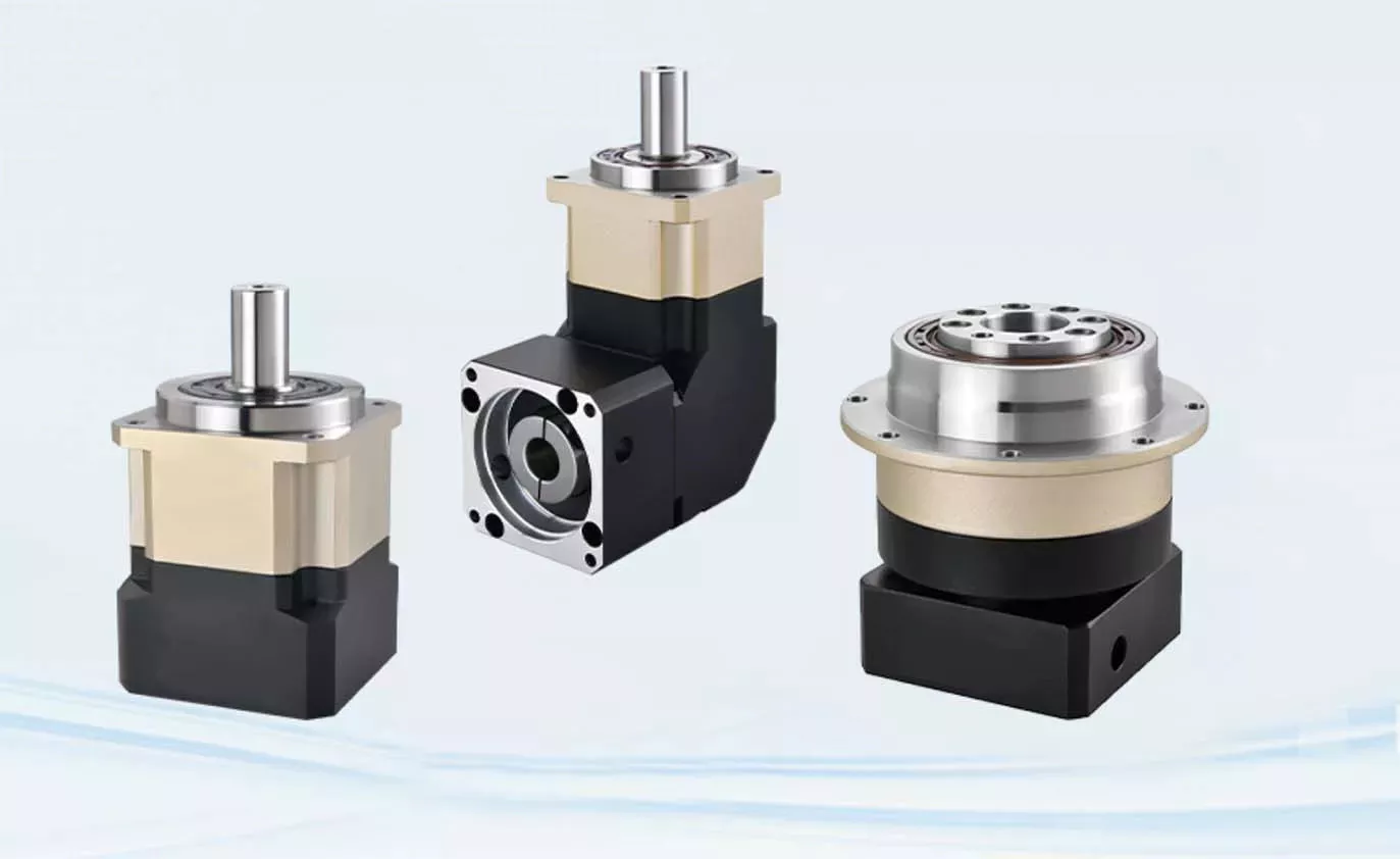
planetary gearboxes
Planetary gearboxes perform on a similar principle to photo voltaic systems. They rotate all around a center gear known as the sun equipment, and two or much more outer gears, called earth gears, are related by a provider. These gears then travel an output shaft. The arrangement of world gears is equivalent to that of the Milky Way’s ring of planets. This arrangement creates the very best torque density and stiffness for a gearbox.
As a compact alternative to typical pinion-and-gear reducers, planetary gearing offers a lot of advantages. These qualities make planetary gearing best for a variety of purposes, including compactness and reduced excess weight. The effectiveness of planetary gearing is increased by the truth that ninety per cent of the input energy is transferred to the output. The gearboxes also have reduced sound and large torque density. In addition, their layout delivers far better load distribution, which contributes to a for a longer time provider daily life.
Planetary gears need lubrication. Since they have a more compact footprint than typical gears, they dissipate warmth properly. In fact, lubrication can even reduced vibration and sound. It is also critical to preserve the gears correctly lubricated to avert the put on and tear that arrives with use. The lubrication in planetary gears also assists preserve them working effectively and reduces use and tear on the gears.
A planetary gearbox utilizes multiple planetary elements to accomplish the reduction aim. Every single equipment has an output shaft and a sunshine gear situated in the middle. The ring gear is mounted to the machine, while the solar equipment is attached to a clamping technique. The outer gears are connected to the provider, and every planetary equipment is held with each other by rings. This arrangement enables the planetary gear to be symmetrical with regard to the enter shaft.
The gear ratio of a planetary gearbox is defined by the solar gear’s quantity of tooth. As the sunshine gear gets smaller sized, the ratio of the equipment will boost. The ratio selection of planetary gears ranges from 3:1 to ten to one. At some point, even so, the sunshine gear turns into as well tiny, and the torque will fall drastically. The greater the ratio, the considerably less torque the gears can transmit. So, planetary gears are often referred to as “planetary” gears.
Their design and style
The fundamental design of a Planetary Gearbox is quite straightforward. It is composed of 3 interconnecting back links, every single of which has its very own torque. The ring equipment is fixed to the frame at O, and the other two are fixed to each other at A and B. The ring equipment, meanwhile, is hooked up to the world arm 3 at O. All 3 elements are linked by joints. A cost-free-human body diagram is shown in Determine 9.
During the improvement approach, the design team will divide the energy to every single individual world into its respective power paths. This distribution will be based mostly on the meshing condition of all gears in the system. Then, the style group will move forward to figure out the masses on person equipment meshes. Using this method, it is feasible to establish the loads on personal gear meshes and the condition of ring equipment housing.
Planetary Gearboxes are made of three gear sorts. The sunshine equipment is the middle, which is linked to the other two gears by an inner tooth ring gear. The earth pinions are arranged in a provider assembly that sets their spacing. The provider also incorporates an output shaft. The a few components in a Planetary Gearbox mesh with each other, and they rotate with each other as one particular. Relying on the software, they may rotate at various speeds or at distinct times.
The planetary gearbox’s design is exclusive. In a planetary gearbox, the input gear rotates about the central gear, even though the outer gears are organized around the sunshine gear. In addition, the ring equipment holds the construction together. A carrier connects the outer gears to the output shaft. In the end, this gear technique transmits higher torque. This kind of gearbox is perfect for higher-speed operations.
The standard design and style of a Planetary Gearbox is composed of multiple contacts that need to mesh with each other. A one world has an integer quantity of tooth, while the ring has a non-integer quantity. The enamel of the planets should mesh with each and every other, as nicely as the solar. The tooth counts, as well as the world spacing, play a function in the design and style. A planetary gearbox should have an integer amount of tooth to purpose effectively.
Programs
In addition to the over-described purposes, planetary gearing is also utilized in device tools, plastic equipment, derrick and dock cranes, and material handling equipments. Even more, its software is discovered in dredging equipment, highway-creating machinery, sugar crystallizers, and mill drives. Although its versatility and effectiveness helps make it a desirable selection for numerous industries, its difficult structure and construction make it a complicated element.
Amongst the a lot of benefits of making use of a planetary gearbox, the potential to transmit increased torque into a controlled room can make it a well-liked choice for several industries. In addition, introducing added earth gears raises the torque density. This tends to make planetary gears suited for purposes necessitating high torque. They are also used in electric powered screwdrivers and turbine engines. Even so, they are not employed in everything. Some of the much more frequent purposes are reviewed below:
One particular of the most essential functions of planetary gearboxes is their compact footprint. They are able to transmit torque although at the very same time reducing noise and vibration. In addition to this, they are able to obtain a substantial speed with no sacrificing large-good quality efficiency. The compact footprint of these gears also enables them to be used in substantial-speed programs. In some cases, a planetary gearbox has sliding sections. Some of these sections are lubricated with oil, even though others may require a synthetic gel. Even with these distinctive attributes, planetary gears have turn into common in many industries.
Planetary gears are composed of a few factors. The sunshine gear is the input gear, whilst the planet gears are the output gears. They are linked by a carrier. The carrier connects the input shaft with the output shaft. A planetary gearbox can be made for different needs, and the type you use will rely on the requirements of your software. Its style and functionality should meet up with your application’s wants.
The ratios of planetary gears range dependent on the variety of planets. The scaled-down the sunlight gear, the greater the ratio. When planetary levels are employed alone, the ratio range is 3:1 to 10:1. Increased ratios can be attained by connecting several planetary levels jointly in the same ring equipment. This strategy is identified as a multi-stage gearbox. However, it can only be used in big gearboxes.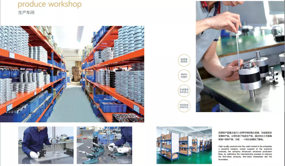
Routine maintenance
The primary part of a planetary gearbox is the planetary equipment. It requires typical routine maintenance and cleansing to continue being in top shape. Need for a longer daily life span shields all other components of the gearbox. This post will examine the maintenance and cleaning processes for planetary gears. After looking through this report, you ought to know how to sustain your planetary gearbox effectively. With any luck ,, you can appreciate a for a longer time life with your gearbox.
To start with, it is crucial to know how to appropriately lubricate a planetary gearbox. The lubricant is essential as gears that function at large speeds are topic to high stages of heat and friction. The housing of the planetary gearbox need to be made to allow the warmth to dissipate. The recommended oil is synthetic, and it should be crammed in between 30 and fifty %. The lubricant must be transformed at least each six months or as required.
Although it may seem needless to replace a planetary gearbox, regular servicing will assist it last a lengthy time. A standard inspection will identify a issue and the proper repairs are needed. Once the planetary gearbox is entire, it will plug with gear oil. To steer clear of this problem, consider obtaining the device fixed instead of changing the gearbox. This can help save you a lot of funds over a new planetary gearbox.
Correct lubrication is essential for a prolonged life of your planetary gearbox. Oil modify frequency must be based mostly on oil temperature and working speed. Oil at larger temperatures ought to be changed far more regularly because it loses its molecular composition and are not able to sort a protective movie. Soon after this, oil filter upkeep should be performed every single couple of months. Lastly, the gearbox oil requirements to be checked frequently and changed when essential.

