Product Description
RV series Characteristics
- RV – Sizes:–150
- Input Options: with input shaft, With Square flange,With Input Flange
- Input Power 0.06 to 11 kW
- RV-Size from 030 to 105 in die-cast aluminium alloy budy and over 110 in cast iron
- Ratios between 5 and 100
- Max torque 1550 N.m and admissible output radial loads max 8771 N
- Aluminium units are supplied complete with synthetic oil and allow for universal mounting positions, with no need to modify lubricant quantity
- Worm wheel: Copper (KK Cu).
- Loading capacity in accordance with: ISO 9001:2015/GB/T 19001-2016
- Size 030 and over are painted with RAL 5571 blue
- Worm gear reducers are available with diffferent combinations: NMRV+NMRV, NMRVpower+NMRV, JWB+NMRV
- NMRV, NRV+VS,NMRV+AS,NMRV+VS,NMRV+F
- Options: torque arm, output flange, viton oil seals, low/high temperature oil, filling/drain/breather/level plug,Small gap
Basic models can be applied to a wide range of power reduction ratios from 5 to 1000.
Warranty: One year from date of delivery.
| WORM GEARBOX | |||||
| SNW SERIES | Output Speed Range: | ||||
| Type | Old Type | Output Torque | Output Shaft Dia. | 14rpm-280rpm | |
| SNW030 | RV030 | 21N.m | φ14 | Applicable Motor Power: | |
| SNW040 | RV040 | 45N.m | φ19 | 0.06kW-11kW | |
| SNW050 | RV050 | 84N.m | φ25 | Input Options1: | |
| SNW063 | RV063 | 160N.m | φ25 | With Inline AC Motor | |
| SNW075 | RV075 | 230N.m | φ28 | Input Options2: | |
| SNW090 | RV090 | 410N.m | φ35 | With Square flange | |
| SNW105 | RV105 | 630N.m | φ42 | Input Options3: | |
| SNW110 | RV110 | 725N.m | φ42 | With Input Shaft | |
| SNW130 | RV130 | 1050N.m | φ45 | Input Options4: | |
| SNW150 | RV150 | 1550N.m | φ50 | With Input Flange |
Starshine Drive
ZheJiang CHINAMFG Drive Co.,Ltd,the predecessor was a state-owned military mould enterprise, was established in 1965. CHINAMFG specializes in the complete power transmission solution for high-end equipment manufacturing industries based on the aim of “Platform Product, Application Design and Professional Service”.
CHINAMFG have a strong technical force with over 350 employees at present, including over 30 engineering technicians, 30 quality inspectors, covering an area of 80000 square CHINAMFG and kinds of advanced processing machines and testing equipments. We have a good foundation for the industry application development and service of high-end speed reducers & variators owning to the provincial engineering technology research center,the lab of gear speed reducers, and the base of modern R&D.
Our Team
Quality Control
Quality:Insist on Improvement,Strive for Excellence With the development of equipment manufacturing indurstry,customer never satirsfy with the current quality of our products,on the contrary,wcreate the value of quality.
Quality policy:to enhance the overall level in the field of power transmission
Quality View:Continuous Improvement , pursuit of excellence
Quality Philosophy:Quality creates value
3. Incoming Quality Control
To establish the AQL acceptable level of incoming material control, to provide the material for the whole inspection, sampling, immunity. On the acceptance of qualified products to warehousing, substandard goods to take return, check, rework, rework inspection; responsible for tracking bad, to monitor the supplier to take corrective measures
to prevent recurrence.
4. Process Quality Control
The manufacturing site of the first examination, inspection and final inspection, sampling according to the requirements of some projects, judging the quality change trend;
found abnormal phenomenon of manufacturing, and supervise the production department to improve, eliminate the abnormal phenomenon or state.
5. FQC(Final QC)
After the manufacturing department will complete the product, stand in the customer’s position on the finished product quality verification, in order to ensure the quality of
customer expectations and needs.
6. OQC(Outgoing QC)
After the product sample inspection to determine the qualified, allowing storage, but when the finished product from the warehouse before the formal delivery of the goods, there is a check, this is called the shipment inspection.Check content:In the warehouse storage and transfer status to confirm, while confirming the delivery of the product
is a product inspection to determine the qualified products.
Packing
Delivery
/* January 22, 2571 19:08:37 */!function(){function s(e,r){var a,o={};try{e&&e.split(“,”).forEach(function(e,t){e&&(a=e.match(/(.*?):(.*)$/))&&1
| Application: | Motor, Machinery |
|---|---|
| Hardness: | Hardened Tooth Surface |
| Installation: | Horizontal Type |
| Layout: | Corner |
| Gear Shape: | Worm and Worm Wheel |
| Step: | Single-Step |
| Customization: |
Available
|
|
|---|

Can you provide insights into the importance of proper installation and alignment of winch drives?
Proper installation and alignment of winch drives are of utmost importance to ensure optimal performance, longevity, and safety of the system. Here’s a detailed explanation of the significance of proper installation and alignment of winch drives:
- Optimal Performance:
Proper installation and alignment are crucial for achieving optimal performance of winch drives. Precise alignment ensures that the winch drive operates within its designed parameters, minimizing power losses and maximizing efficiency. Accurate installation of components, such as motors, gearboxes, and brakes, ensures that they are properly integrated and aligned with each other. This alignment reduces mechanical stress, minimizes friction, and allows for smooth and reliable operation of the winch drive, resulting in improved performance and productivity.
- Extended Lifespan:
The correct installation and alignment of winch drives contribute to their longevity. When components are misaligned or improperly installed, it can lead to excessive wear, vibration, and premature failure of critical parts. Misalignment puts additional stress on bearings, shafts, gears, and other components, causing accelerated wear and reducing their lifespan. By ensuring proper alignment during installation, the load is distributed evenly, reducing mechanical stress and increasing the lifespan of the winch drive system.
- Reduced Maintenance and Downtime:
Proper installation and alignment can significantly reduce the need for maintenance and minimize downtime. Misalignment or improper installation can cause issues such as excessive heat generation, increased friction, and misoperation of safety mechanisms. These issues can lead to frequent breakdowns and unplanned downtime, resulting in productivity losses and increased maintenance costs. By ensuring correct alignment and installation, the risk of such issues is minimized, reducing the frequency of maintenance and improving overall system uptime.
- Enhanced Safety:
The safety of personnel and equipment is a critical consideration when it comes to winch drives. Improper installation and alignment can compromise the safety of the system. Misalignment can result in unexpected movements, excessive vibrations, or loss of control, posing risks to both operators and the surrounding environment. Proper alignment ensures that the winch drive operates within its intended parameters, reducing the likelihood of malfunctions, accidents, or equipment damage. It is essential to follow manufacturer guidelines and industry standards for installation and alignment to maintain a safe working environment.
- Efficient Power Transmission:
Correct alignment of winch drives ensures efficient power transmission from the motor to the drum or load. Misalignment can lead to power losses, increased energy consumption, and reduced overall system efficiency. Proper alignment ensures that the power is transmitted smoothly and efficiently, minimizing energy wastage and optimizing the performance of the winch drive. This not only improves energy efficiency but also reduces operating costs over the lifespan of the system.
In summary, the proper installation and alignment of winch drives are essential for achieving optimal performance, extending the lifespan of the system, reducing maintenance and downtime, enhancing safety, and ensuring efficient power transmission. Following manufacturer guidelines, industry standards, and engaging experienced professionals during installation and alignment processes is crucial to maximize the benefits and longevity of winch drive systems.

What factors should be considered when selecting a winch drive for specific applications?
When selecting a winch drive for specific applications, several factors need to be considered to ensure optimal performance and compatibility. Here’s a detailed explanation of the key factors that should be taken into account:
- Load Capacity:
The load capacity is one of the most critical factors to consider when selecting a winch drive. It refers to the maximum weight or force that the winch can handle safely and efficiently. It’s essential to evaluate the anticipated loads in the specific application and choose a winch drive with a sufficient load capacity to handle those loads. Selecting a winch drive with inadequate load capacity can result in safety hazards, reduced performance, and potential damage to the winch or the load being lifted or pulled.
- Power Source:
The power source of the winch drive is another crucial consideration. Winch drives are available in electric, hydraulic, and pneumatic variants, each with its own advantages and limitations. The choice of power source depends on factors such as the availability of power, the required pulling power, and the specific application’s environmental conditions. Electric winch drives are commonly used due to their ease of use and versatility. Hydraulic winch drives offer high pulling power for heavy-duty applications, while pneumatic winch drives are suitable for hazardous or explosive environments where electrical components are not permitted.
- Control Mechanisms:
The control mechanisms of the winch drive play a significant role in the efficiency and ease of operation. Consider the control options available for the winch drive, such as manual control, remote control, or integrated control systems. Remote control systems, for example, allow operators to control the winch drive from a safe distance, enhancing safety and flexibility. Additionally, some winch drives offer features like variable speed control, which allows for precise positioning and controlled movement of the load.
- Environmental Conditions:
The environmental conditions in which the winch drive will be used should be carefully assessed. Some winch drives are designed to withstand harsh environments, such as extreme temperatures, moisture, dust, or corrosive substances. For example, in marine applications, winch drives need to be corrosion-resistant and capable of operating in wet and salty conditions. Assessing the specific environmental conditions and selecting a winch drive with appropriate protection and durability features ensures its longevity and reliable performance.
- Mounting and Installation:
The mounting and installation requirements of the winch drive should be considered to ensure proper integration into the intended application. Evaluate factors such as space availability, mounting options (e.g., vehicle-mounted, structure-mounted, or portable), and compatibility with existing equipment or systems. Some winch drives may require additional accessories or modifications for installation, so it’s important to factor in these considerations during the selection process.
- Safety Features:
Winch drives should be equipped with appropriate safety features to prevent accidents and ensure secure operation. Common safety features include overload protection, emergency stop mechanisms, limit switches, and braking systems for load holding. These safety features contribute to the safe operation of the winch drive and protect against potential hazards or damage caused by excessive loads or unexpected circumstances.
- Reliability and Maintenance:
Consider the reliability and maintenance requirements of the winch drive. Look for winch drives from reputable manufacturers known for producing high-quality and reliable equipment. Assess factors such as maintenance intervals, ease of maintenance, availability of spare parts, and after-sales support. Choosing a winch drive that is reliable and has accessible maintenance options ensures minimal downtime and long-term cost-effectiveness.
By considering these factors when selecting a winch drive for specific applications, you can make an informed decision that aligns with the load requirements, power source availability, control preferences, environmental conditions, and safety considerations of your intended application.

Can you explain the key components and functions of a winch drive mechanism?
A winch drive mechanism consists of several key components that work together to provide controlled pulling or lifting capabilities. Each component has a specific function that contributes to the overall operation of the winch drive. Here’s a detailed explanation of the key components and their functions:
- Power Source:
The power source is the component that provides the energy to drive the winch mechanism. It can be an electric motor, hydraulic system, or even a manual crank. Electric motors are commonly used in modern winches due to their efficiency, controllability, and ease of operation. Hydraulic systems are often employed in heavy-duty winches that require high pulling capacities. Manual winches, operated by hand-cranking, are typically used in lighter applications or as backup systems. The power source converts the input energy into rotational motion, which drives the other components of the winch mechanism.
- Gearbox or Transmission:
The gearbox or transmission is responsible for controlling the speed and torque output of the winch drive. It consists of a series of gears arranged in specific ratios. The gears are engaged or disengaged to achieve the desired speed and torque requirements for the application. The gearbox allows the winch drive to provide both high pulling power or low-speed precision, depending on the needs of the task. It also helps distribute the load evenly across the gear teeth, ensuring smooth and reliable operation.
- Drum or Spool:
The drum or spool is a cylindrical component around which the cable or rope is wound. It is typically made of steel or other durable materials capable of withstanding high tension forces. The drum is connected to the rotational output of the gearbox or transmission. As the gearbox rotates, the drum winds or unwinds the cable, depending on the direction of rotation. The diameter of the drum determines the pulling or lifting capacity of the winch drive. A larger drum diameter allows for a greater length of cable to be wound, resulting in increased pulling power.
- Cable or Rope:
The cable or rope is the element that connects the winch drive to the load being pulled or lifted. It is typically made of steel wire or synthetic materials with high tensile strength. The cable is wound around the drum and extends out to the anchor point or attachment point of the load. It acts as the link between the winch drive and the object being moved. The choice of cable or rope depends on the specific application requirements, such as the weight of the load, environmental conditions, and desired flexibility.
- Braking System:
A braking system is an essential component of a winch drive mechanism to ensure safe and controlled operation. It prevents the cable or rope from unwinding uncontrollably when the winch is not actively pulling or lifting a load. The braking system can be mechanical or hydraulic, and it engages automatically when the winch motor is not applying power. It provides a secure hold and prevents the load from slipping or releasing unintentionally. The braking system also helps control the descent of the load during lowering operations, preventing sudden drops or free-falls.
- Control System:
The control system allows the operator to manage the operation of the winch drive. It typically includes controls such as switches, buttons, or levers that enable the activation, direction, and speed control of the winch. The control system can be integrated into the winch housing or provided as a separate control unit. In modern winches, electronic control systems may offer additional features such as remote operation, load monitoring, and safety interlocks. The control system ensures precise and safe operation, allowing the operator to adjust the winch drive according to the specific requirements of the task.
In summary, a winch drive mechanism consists of key components such as the power source, gearbox or transmission, drum or spool, cable or rope, braking system, and control system. The power source provides the energy to drive the winch, while the gearbox controls the speed and torque output. The drum or spool winds or unwinds the cable, which connects the winch drive to the load. The braking system ensures safe and controlled operation, and the control system allows the operator to manage the winch’s performance. Together, these components enable winch drives to provide controlled pulling or lifting capabilities in a wide range of applications.


editor by Dream 2024-05-08
China Input Shaft Nmrv150 Worm Gearbox Speed Reduction with Great quality
Solution Description
Qualities:
(1)Huge output torque
(2) Secure, reputable, affordable and durable
(3) Secure transmission, quiet operation
(4)Substantial heat-radiating efficiency, higher carrying capacity
(5) Blend of 2 one-step worm gear speed reducers, conference the requirements of super speed ratio
Technological knowledge:
(1) Iput electricity:.06kw-15kw
(2) Output torque:4-2320N.M
(3) Pace ratio: 5/10/fifteen/twenty/25/30/40/fifty/sixty/80/100
(4) With IEC enter flange: 56B14/71B14/80B5/90B5…
Supplies:
(1) NMRV571-NMRV090: Aluminium alloy housing
(2) NMRV110-one hundred fifty: Forged iron housing
(3) Bearing: CZPT bearing & Selfmade bearing
(4) Lubricant: Synthetic & Mineral
Coloration:
(1) Blue / Gentle blue
(2) Silvery White
Quality handle
(1) Good quality assure: 1 yr
(2) Certificate of top quality: ISO9001:2000
(3) Each product have to be analyzed ahead of sendingv
|
US $280 / Piece | |
1 Piece (Min. Order) |
###
| Application: | Motor, Electric Cars, Motorcycle, Machinery, Marine, Toy, Agricultural Machinery, Car |
|---|---|
| Hardness: | Hardened Tooth Surface |
| Installation: | 90 Degree |
| Layout: | Expansion |
| Gear Shape: | Cylindrical Gear |
| Step: | Single-Step |
###
| Customization: |
Available
|
|---|
|
US $280 / Piece | |
1 Piece (Min. Order) |
###
| Application: | Motor, Electric Cars, Motorcycle, Machinery, Marine, Toy, Agricultural Machinery, Car |
|---|---|
| Hardness: | Hardened Tooth Surface |
| Installation: | 90 Degree |
| Layout: | Expansion |
| Gear Shape: | Cylindrical Gear |
| Step: | Single-Step |
###
| Customization: |
Available
|
|---|
Planetary Gearbox Advantages and Disadvantages
A planetary gearbox is a type of mechanical drive with a single output shaft. They are suitable for both clockwise and counterclockwise rotations, have less inertia, and operate at higher speeds. Here are some advantages and disadvantages of this type of gearbox. Let us see what these advantages are and why you should use them in your applications. Listed below are some of the benefits of planetary gearboxes.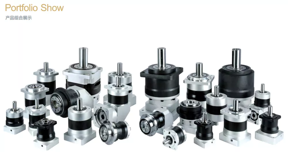
Suitable for counterclockwise and clockwise rotation
If you want to teach children about the clock hands, you can buy some resources for counterclockwise and asymmetrical rotation. These resources include worksheets for identifying degrees of rotation, writing rules for rotation, and visual processing. You can also use these resources to teach angles. For example, the translation of shapes activity pack helps children learn about the rotation of geometric shapes. Similarly, the visual perception activity sheet helps children understand how to process information visually.
Various studies have been done to understand the anatomical substrate of rotations. In a recent study, CZPT et al. compared the position of the transitional zone electrocardiographically and anatomically. The authors found that the transitional zone was normal in nine of 33 subjects, indicating that rotation is not a sign of disease. Similarly, a counterclockwise rotation may be caused by a genetic or environmental factor.
The core tip data should be designed to work in both clockwise and counterclockwise rotation. Counterclockwise rotation requires a different starting point than a clockwise rotation. In North America, star-delta starting is used. In both cases, the figure is rotated about its point. Counterclockwise rotation, on the other hand, is done in the opposite direction. In addition, it is possible to create counterclockwise rotation using the same gimbal.
Despite its name, both clockwise and counterclockwise rotation requires a certain amount of force to rotate. When rotating clockwise, the object faces upwards. Counterclockwise rotation, on the other hand, starts from the top position and heads to the right. If rotating in the opposite direction, the object turns counterclockwise, and vice versa. The clockwise movement, in contrast, is the reverse of counterclockwise rotation.
Has less inertia
The primary difference between a planetary gearbox and a normal pinion-and-gear reducer is the ratio. A planetary gearbox will produce less inertia, which is an important advantage because it will reduce torque and energy requirements. The ratio of the planetary gearbox to its fixed axis counterpart is a factor of three. A planetary gearbox has smaller gears than a conventional planetary, so its inertia is proportional to the number of planets.
Planetary gears are less inertia than spur gears, and they share the load across multiple gear teeth. This means that they will have low backlash, and this is essential for applications with high start-stop cycles and frequent rotational direction changes. Another benefit is the high stiffness. A planetary gearbox will have less backlash than a spur gearbox, which means that it will be more reliable.
A planetary gearbox can use either spur or helical gears. The former provides higher torque ratings while the latter has less noise and stiffness. Both types of gears are useful in motorsports, aerospace, truck transmissions, and power generation units. They require more assembly time than a conventional parallel shaft gear, but the PD series is the more efficient alternative. PD series planetary gears are suitable for many applications, including servo and robotics.
In contrast, a planetary gear set can have varying input speed. This can affect the frequency response of the gearset. A mathematical model of the two-stage planetary gears has non-stationary effects and correlates with experimental findings. Fig. 6.3 shows an addendum. The dedendum’s minimum value is approximately 1.25m. When the dedendum is at its smallest, the dedendum has less inertia.
Offers greater reliability
The Planetary Gearbox is a better option for driving a vehicle than a standard spur gearbox. A planetary gearbox is less expensive, and they have better backlash, higher load capacity, and greater shock loads. Unlike spur gearboxes, however, mechanical noise is virtually nonexistent. This makes them more reliable in high-shock situations, as well as in a wide range of applications.
The Economy Series has the same power density and torque capacity of the Precision Helical Series, but it lacks the precision of the latter. In contrast, Economy Series planetary gearboxes feature straight spur planetary gearing, and they are used in applications requiring high torque. Both types of gearboxes are compatible with NEMA servo motors. If torque density is important, a planetary gearbox is the best choice.
The Dispersion of External Load: The SSI model has been extensively used to model the reliability of planetary gear systems. This model takes the contact force and fatigue strength of the system as generalized stress and strength. It also provides a theoretical framework to evaluate the reliability of planetary gear systems. It also has many other advantages that make it the preferred choice for high-stress applications. The Planetary Gearbox offers greater reliability and efficiency than traditional rack and pinion gear systems.
Planetary gearing has greater reliability and compact design. Its compact design allows for wider applications with concerns about space and weight. Additionally, the increased torque and reduction makes planetary gearboxes an excellent choice for a wide variety of applications. There are three major types of planetary gearboxes, each with its own advantages. This article describes a few of them. Once you understand their workings, you will be able to choose the best planetary gearbox for your needs.
Has higher operating speeds
When you look at planetary gearboxes, you might be confused about which one to choose. The primary issue is the application of the gearbox. You must also decide on secondary factors like noise level, corrosion resistance, construction, price, and availability worldwide. Some constructors work faster than others and deliver the gearboxes on the same day. However, the latter ones often deliver the planetary gearbox out of stock.
Compared to conventional gearboxes, a planetary gearbox can run at higher speeds when the input speed fluctuates. However, these gears are not very efficient in high-speed applications because of their increased noise levels. This makes planetary gears unsuitable for applications involving a great deal of noise. That is why most planetary gears are used in small-scale applications. There are some exceptions, but in general, a planetary gearbox is better suited for applications with higher operating speeds.
The basic planetary gearbox is a compact alternative to normal pinion-and-gear reducers. They can be used in a wide variety of applications where space and weight are concerns. Its efficiency is also higher, delivering 97% of the power input. It comes in three different types based on the performance. A planetary gearbox can also be classified as a worm gear, a spur gear, or a sprocket.
A planetary gearhead has a high-precision design and can generate substantial torque for their size. It also reduces backlash to two arc-min. Additionally, it is lubricated for life, which means no maintenance is needed. It can fit into a small machine envelope and has a small footprint. Moreover, the helical crowned gearing provides fast positioning. A sealed gearbox prevents abrasive dust from getting into the planetary gearhead.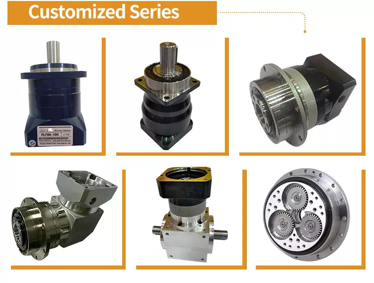
Has drawbacks
The design of a planetary gearbox is compact and enables high torque and load capability in a small space. This gear arrangement also reduces the possibility of wear and tear. Planet gears are arranged in a planetary fashion, allowing gears to shift under load and a uniform distribution of torque. However, some disadvantages of planetary gears must be considered before investing in this gearbox.
While the planetary gearbox is a high precision motion-control device, its design and maintenance requirements are a concern. The bearing load is high, requiring frequent lubrication. Also, they are inaccessible. Despite these drawbacks, planetary gearboxes are suitable for a variety of tasks. They also have low backlash and high torsional stiffness, making them excellent choices for many applications.
As a result, the speed of a planetary gearbox varies with load and speed. At lower ratios, the sun gear becomes too large in relation to the planet gears. As the ratio increases, the sun gear will become too low, reducing torque. The planetary gears also reduce their torque in high-speed environments. Consequently, the ratio is a crucial consideration for planetary gearbox condition monitoring.
Excess drag may result from out-of-tolerance components or excessive lubrication. Drag should be measured both in directions and be within acceptable ranges. Grease and oil lubrication are two common planetary gearbox lubricants, but the choice is largely dependent on your application. While grease lubricates planetary gears well, oil needs maintenance and re-lubrication every few thousand hours.


editor by czh 2023-01-09