Product Description
Product Description
Product Description:
|
Model |
Socare 1
|
Place of Origin |
HangZhou,China |
|
Brand |
Slewing Drive |
Delivery Time |
7 days |
|
Material |
42CrMo,50Mn |
Output Torque |
1.46kN.m |
|
Tilting Moment Torque |
13.5kN.m |
Holding Torque |
10.4kN.m |
|
Static Axial Rating |
133KN |
Static Radial Rating |
53KN |
|
Dynamic Axial Rating |
32KN |
Dynamic Radial Rating |
28 KN |
|
Gear Ratio |
71:1 |
Efficiency |
40% |
|
Hydraulic Motor |
Yes |
HS Code |
8483457190 |
Slewing Drive
The title of Slewing Drive is no uniform, it also called: Slewing gear, rotary drive, rotary drive axle, rotary drive vice, slew drive, slewing gear, and rotary drive unit. At present the majority of such devices: The Slewing Drive.
In addition to the field of use in the daily solar power systems are usually used for Special vehicle, heavy-duty flat-panel truck, container cranes, truck mounted crane, automobile crane and aerial vehicles, cranes, gantry cranes, small wind power stations, space communications, satellite receiver, etc. . The Slewing Drive in the solar photovoltaic industry, the general configuration DC planetary reduction motor or AC geared motors; Main configuration of the hydraulic motor as a power-driven construction machinery.
Rotary speed reducer/slewing drive Main fetures:
1.large speed ratio range
2.small volume,low weight ,saving space for mounting.
3.high efficiency,high mechanical strength and high quality aluminum alloy housing
4.long life service,large output torque,low noise and little vibration
5.low temperature rise,omnibearing installation ,easy to connect with other machinery.
6.high carry ability,elegant apperance.
7.CE standard,input power can be 0.06KW-15KW
8.stable transmission
Socare Slewing Drives Features:
Socare Slewing drive is a special bearing. And a slewing drive usually consist of slewing bearing, worm shaft, housing, bearing, motor and so on.
Motor drive the worm shaft, the outer ring of slewing bearing will rotate, the outer ring output the torque through flange while the inner ring of slewing bearing is fixed in housing. Installation space savings advantages to a greater extent.
Application:
Slewing drives are widely used in aerospace area, solar power systems, wind turbines, satellite broadcasting system, and engineering machinery like truck cranes, and man lifts, etc. Recently years, it has been prosperously used in photovoltaic power generation systems, special vehicle, heavy-duty flat-panel truck, container cranes, truck mounted crane, automobile crane and aerial vehicles, cranes, gantry cranes, small wind power stations, space communications, satellite receiver, etc.
Our Advantages
Our Advantage:
1. Double skeleton oil seal structure, sealing performance reaches IP65, which can meet long-term outdoor use.
2. The surface of the slewing bearing adopts high-quality galvanized or QPQ treatment process, which has good corrosion resistance.
3. Worm gear meshing, high precision, large tooth contact area, high transmission torque, suitable for low speed and high torque applications.
4. Customized solutions to meet different application conditions.
Packaging & Shipping
/* May 10, 2571 16:49:51 */!function(){function d(e,r){var a,o={};try{e&&e.split(“,”).forEach(function(e,t){e&&(a=e.match(/(.*?):(.*)$/))&&1

How do winch drives contribute to the adaptability and versatility of mechanical systems in various settings?
Winch drives play a significant role in enhancing the adaptability and versatility of mechanical systems in various settings. Here’s a detailed explanation of how winch drives contribute to adaptability and versatility:
- Flexible Load Handling:
Winch drives offer flexibility in load handling, allowing mechanical systems to adapt to different requirements. They can handle a wide range of loads, from light to heavy, and provide precise control over the lifting, lowering, and positioning of loads. The ability to adjust the speed, torque, and direction of the winch drive enables it to accommodate different load characteristics and operational needs. This flexibility makes winch drives suitable for a variety of applications, including construction, manufacturing, marine, entertainment, and transportation industries.
- Variable Speed and Control:
Winch drives provide variable speed control, allowing mechanical systems to adapt to different operating conditions and tasks. The speed of the winch drive can be adjusted to match the specific requirements of the application, whether it involves slow and precise movements or fast and efficient operations. Additionally, winch drives offer precise control over acceleration, deceleration, and stopping, enabling smooth and controlled movements. This variable speed and control capability enhance the adaptability and versatility of mechanical systems in handling diverse tasks and operating in different environments.
- Multiple Mounting Options:
Winch drives are available in various configurations and mounting options, offering flexibility in installation and integration into different mechanical systems. They can be mounted horizontally, vertically, or at custom angles, depending on the specific requirements of the application. This versatility in mounting options allows winch drives to be easily incorporated into existing systems or adapted to fit space constraints in different settings. Whether it’s a stationary installation, mobile equipment, or overhead lifting system, winch drives can be positioned and mounted in a way that optimizes their functionality and adaptability.
- Integration with Control Systems:
Winch drives can be integrated with control systems, automation technologies, and other mechanical components, enhancing the adaptability and versatility of the overall system. They can be connected to programmable logic controllers (PLCs), human-machine interfaces (HMIs), or central control systems, enabling seamless integration and coordination with other equipment and processes. This integration allows for synchronized operations, centralized control, and automation of complex tasks, making the mechanical system more adaptable to changing requirements and versatile in different settings.
- Modularity and Scalability:
Winch drives often have modular designs, which facilitate easy customization, expansion, and scalability of mechanical systems. Additional winch drives can be added or existing ones can be reconfigured to accommodate changing load capacities or operational needs. This modularity allows mechanical systems to adapt to evolving requirements without significant redesign or replacement of the entire system. It provides the flexibility to scale up or down the capabilities of the system, making it versatile and adaptable to different settings and applications.
In summary, winch drives contribute to the adaptability and versatility of mechanical systems through their flexible load handling capabilities, variable speed and control, multiple mounting options, integration with control systems, and modularity. By incorporating winch drives, mechanical systems can adapt to different tasks, environments, and operational demands, making them versatile and suitable for a wide range of settings and applications.
Can you provide examples of products or machinery that commonly use winch drives?
Winch drives are widely used in various industries and applications where lifting, pulling, or positioning heavy loads is required. They offer a versatile and efficient solution for numerous tasks. Here are some examples of products or machinery that commonly use winch drives:
- Cranes:
Winch drives are an integral part of cranes used in construction, manufacturing, and shipping industries. They enable the lifting and lowering of loads, as well as the movement of crane booms and jibs. Cranes such as mobile cranes, tower cranes, and overhead cranes rely on winch drives for their lifting capabilities.
- Elevators and Lifts:
Winch drives are used in elevators and lifts to vertically transport people or goods between different levels of buildings or structures. They provide the necessary lifting force for the elevator car or lift platform, allowing smooth and controlled vertical movement.
- Marine Equipment:
Winch drives are commonly found in various marine equipment and vessels. They are used in shipboard cranes, davits, anchor handling winches, mooring winches, and fishing equipment. Winch drives play a crucial role in the handling of heavy equipment, cargo, and anchoring operations in marine environments.
- Offshore and Oil Rig Applications:
In offshore and oil rig applications, winch drives are utilized for various tasks. They are used in winches for launching and recovering subsea equipment, handling pipes and cables, and positioning heavy loads on offshore platforms. Winch drives are also employed in drilling equipment for operations such as raising and lowering the drilling string.
- Material Handling Equipment:
A wide range of material handling equipment relies on winch drives for lifting and pulling operations. This includes hoists, winch trucks, forklifts, conveyor systems, and overhead cranes used in warehouses, manufacturing facilities, and construction sites. Winch drives enable efficient and controlled movement of heavy materials and equipment.
- Entertainment Industry:
The entertainment industry extensively uses winch drives for stage rigging, theatrical productions, and concert setups. Winch drives are employed to move and control stage elements, lighting fixtures, sound equipment, and special effects. They allow for dynamic and precise positioning of equipment during performances.
- Automotive Recovery and Towing:
Winch drives are commonly used in recovery and towing equipment for vehicles. They are mounted on trucks or trailers and provide the pulling force necessary to recover stuck or immobilized vehicles. Winch drives are also utilized in off-road vehicles and ATV (All-Terrain Vehicle) winches for self-recovery or assisting others.
- Agricultural Machinery:
In the agricultural sector, winch drives are employed in various machinery such as agricultural sprayers, irrigation systems, and harvesting equipment. They facilitate the movement and positioning of equipment, as well as the lifting and lowering of heavy loads, enhancing efficiency in farming operations.
These examples illustrate the wide-ranging applications of winch drives across different industries. Their versatility and adaptability make them essential components in various products and machinery that involve lifting, pulling, or positioning heavy loads.
How does the design of a winch drive contribute to efficient load lifting and pulling?
The design of a winch drive plays a critical role in ensuring efficient load lifting and pulling operations. Various design considerations are implemented to optimize performance, reliability, and safety. Here’s a detailed explanation of how the design of a winch drive contributes to efficient load lifting and pulling:
- Power and Torque:
A well-designed winch drive is equipped with a power source and gearbox that provide sufficient power and torque to handle the intended load. The power source, whether it’s an electric motor or hydraulic system, should have adequate capacity to generate the required energy for the pulling or lifting operation. The gearbox or transmission is designed to provide the appropriate torque output, matching the load requirements. By ensuring the winch drive has the necessary power and torque, it can efficiently handle the load without straining the components or compromising performance.
- Gearing and Speed Control:
The gearing system within the winch drive allows for precise control over the speed of the pulling or lifting operation. The gearbox is designed with different gear ratios, enabling the operator to select the desired speed based on the specific requirements of the task. This capability is crucial for efficient load handling. For instance, a higher gear ratio can be used for lighter loads or faster pulling speeds, while a lower gear ratio provides increased pulling power for heavier loads. The ability to control the speed optimizes the efficiency of the winch drive by adapting to the load characteristics and operational needs.
- Drum Size and Cable Capacity:
The design of the winch drive includes considerations for the drum size and cable capacity. The drum is responsible for winding or unwinding the cable during the pulling or lifting operation. A larger drum diameter allows for a greater length of cable to be wound, which increases the pulling capacity of the winch. The drum design should also ensure proper cable alignment and smooth winding to prevent cable damage or entanglement. By optimizing the drum size and cable capacity, the winch drive can efficiently handle the load and accommodate the necessary cable length required for the task.
- Braking System:
An efficient winch drive incorporates a reliable braking system. The braking system is designed to hold the load securely when the winch is not actively pulling or lifting. It prevents the load from slipping or releasing unintentionally, ensuring safety and stability during operation. The braking system should engage quickly and provide sufficient holding force, even in the event of power loss or sudden load changes. A well-designed braking system contributes to the efficiency of load lifting and pulling by maintaining control and preventing accidents or damage.
- Control System and Safety Features:
The design of the winch drive includes a control system with intuitive controls and safety features. The control system allows the operator to manage the operation of the winch drive, including start/stop functions, direction control, and speed adjustment. Clear and user-friendly controls enhance operational efficiency and facilitate precise load handling. Additionally, safety features such as overload protection, emergency stop mechanisms, and limit switches are integrated into the winch drive design to ensure safe operation and prevent damage to the equipment or injury to personnel.
By considering power and torque requirements, gearing and speed control, drum size and cable capacity, braking systems, control systems, and safety features, the design of a winch drive contributes to efficient load lifting and pulling. These design elements work together to optimize performance, control, and safety, allowing the winch drive to handle loads effectively and reliably in various applications and industries.
<img src="https://img.hzpt.com/img/gearbox/gearbox-l1.webp" alt="China Standard Dual-Worm Robust Electrical Motor Slewing Drive Gear Motor Reducer “><img src="https://img.hzpt.com/img/gearbox/gearbox-l2.webp" alt="China Standard Dual-Worm Robust Electrical Motor Slewing Drive Gear Motor Reducer “>
editor by Dream 2024-10-15
China Standard Industrial Worm Gear Reducer with Hollow Shaft
Product Description
S series Helical Geared Motor Characteristics
1. Features:
- High efficiency: 75%-80%;
- High technology: the helical gear and a worm gear combined with an integrated transmission to improve the torque and efficiency.
- High precision: the gear is made of high-quality alloy steel forging, carbonitriding and hardening treatment, grinding process to ensure high precision and stable running.
- High interchangeability: highly modular, serial design, strong versatility and interchangeability.
2. Technical parameters
| Ratio | 6.8-288 |
| Input power | 0.12-22KW |
| Output torque | 11-4530N.m |
| Output speed | 5-206rpm |
| Mounting type | Foot mounted, foot mounted with CHINAMFG shaft, output flange mounted, hollow shaft mounted, B5 flange mounted with hollow shaft, foot mounted with hollow shaft, B14 flange mounted with hollow shaft, foot mounted with splined hole, foot mounted with shrink disk, hollow shaft mounted with anti-torque arm. |
| Input Method | Flange input(AM), shaft input(AD), inline AC motor input, or AQA servo motor |
| Brake Release | HF-manual release(lock in the brake release position), HR-manual release(autom-atic braking position) |
| Thermistor | TF(Thermistor protection PTC thermisto) TH(Thermistor protection Bimetal swotch) |
| Mounting Position | M1, M2, M3, M4, M5, M6 |
| Type | S37-S97 |
| Output shaft dis. | 20mm, 25mm, 30mm, 35mm, 40mm, 50mm, 60mm, 70mm, |
| Housing material | HT200 high-strength cast iron from R37,47,57,67,77,87 |
| Housing material | HT250 High strength cast iron from R97 107,137,147, 157,167,187 |
| Heat treatment technology | carbonitriding and hardening treatment |
| Single Stage Efficiency | 75%-80% |
| Lubricant | VG220 |
| Protection Class | IP55, F class |
About Us
ZheJiang CHINAMFG Drive Co.,Ltd,the predecessor was a state-owned military mould enterprise, was established in 1965. CHINAMFG specializes in the complete power transmission solution for high-end equipment manufacturing industries based on the aim of “Platform Product, Application Design and Professional Service”.
CHINAMFG have a strong technical force with over 350 employees at present, including over 30 engineering technicians, 30 quality inspectors, covering an area of 80000 square CHINAMFG and kinds of advanced processing machines and testing equipments. We have a good foundation for the industry application development and service of high-end speed reducers & variators owning to the provincial engineering technology research center,the lab of gear speed reducers, and the base of modern R&D.
Our Team
Quality Control
Quality:Insist on Improvement,Strive for Excellence With the development of equipment manufacturing indurstry,customer never satirsfy with the current quality of our products,on the contrary,wcreate the value of quality.
Quality policy:to enhance the overall level in the field of power transmission
Quality View:Continuous Improvement , pursuit of excellence
Quality Philosophy:Quality creates value
3. Incoming Quality Control
To establish the AQL acceptable level of incoming material control, to provide the material for the whole inspection, sampling, immunity. On the acceptance of qualified products to warehousing, substandard goods to take return, check, rework, rework inspection; responsible for tracking bad, to monitor the supplier to take corrective
measures to prevent recurrence.
4. Process Quality Control
The manufacturing site of the first examination, inspection and final inspection, sampling according to the requirements of some projects, judging the quality change trend;
found abnormal phenomenon of manufacturing, and supervise the production department to improve, eliminate the abnormal phenomenon or state.
5. FQC(Final QC)
After the manufacturing department will complete the product, stand in the customer’s position on the finished product quality verification, in order to ensure the quality of
customer expectations and needs.
6. OQC(Outgoing QC)
After the product sample inspection to determine the qualified, allowing storage, but when the finished product from the warehouse before the formal delivery of the goods, there is a check, this is called the shipment inspection.Check content:In the warehouse storage and transfer status to confirm, while confirming the delivery of the
product is a product inspection to determine the qualified products.
7. Certification.
Packing
Delivery
/* January 22, 2571 19:08:37 */!function(){function s(e,r){var a,o={};try{e&&e.split(“,”).forEach(function(e,t){e&&(a=e.match(/(.*?):(.*)$/))&&1
| Application: | Motor, Machinery, Agricultural Machinery |
|---|---|
| Function: | Distribution Power, Change Drive Torque, Change Drive Direction, Speed Changing, Speed Reduction |
| Layout: | Cycloidal |
| Hardness: | Hardened Tooth Surface |
| Installation: | Horizontal Type |
| Step: | Three-Step |
| Customization: |
Available
|
|
|---|

Can you explain the impact of winch drives on the overall efficiency of lifting systems?
The efficiency of lifting systems is significantly influenced by the choice and performance of winch drives. Winch drives play a crucial role in converting power into mechanical work to lift or move heavy loads. Here’s a detailed explanation of the impact of winch drives on the overall efficiency of lifting systems:
- Power Transmission:
Winch drives are responsible for transmitting power from the energy source to the lifting mechanism. The efficiency of power transmission directly affects the overall efficiency of the lifting system. Well-designed winch drives minimize power losses due to friction, heat generation, or mechanical inefficiencies. By optimizing the gear system, bearings, and other mechanical components, winch drives can maximize power transmission efficiency and minimize energy waste.
- Mechanical Advantage:
Winch drives provide a mechanical advantage that allows the lifting system to handle heavier loads with less effort. The mechanical advantage is determined by the gear ratio and drum diameter of the winch drive. By selecting an appropriate gear ratio, the winch drive can multiply the input torque, enabling the lifting system to overcome the resistance of the load more efficiently. A higher mechanical advantage reduces the strain on the power source and improves the overall efficiency of the lifting system.
- Speed Control:
Winch drives offer speed control capabilities, allowing operators to adjust the lifting speed according to the specific requirements of the task. The ability to control the lifting speed is essential for efficient and safe operation. By utilizing winch drives with precise speed control mechanisms, the lifting system can optimize the speed to match the load, reducing unnecessary energy consumption and increasing overall efficiency.
- Load Distribution:
Winch drives play a vital role in distributing the load evenly across the lifting system. Uneven load distribution can lead to excessive stress on certain components, reducing the overall efficiency and potentially causing equipment failure. Well-designed winch drives ensure that the load is distributed evenly, minimizing stress concentrations and maximizing the efficiency of the lifting system.
- Control and Safety Features:
Winch drives incorporate control and safety features that contribute to the overall efficiency of the lifting system. Advanced control systems allow for precise positioning and smooth operation, minimizing unnecessary movements and reducing energy consumption. Safety features, such as overload protection or emergency stop mechanisms, help prevent accidents and equipment damage, ensuring uninterrupted and efficient operation of the lifting system.
- Reliability and Maintenance:
The reliability and maintenance requirements of winch drives directly impact the overall efficiency of lifting systems. Well-designed winch drives with robust construction and quality components minimize the risk of breakdowns or unplanned downtime. Additionally, winch drives that are easy to maintain and service reduce the time and resources required for maintenance, maximizing the uptime and efficiency of the lifting system.
In summary, the choice and performance of winch drives have a significant impact on the overall efficiency of lifting systems. By optimizing power transmission, providing a mechanical advantage, offering speed control, ensuring load distribution, incorporating control and safety features, and prioritizing reliability and maintenance, winch drives can enhance the efficiency, productivity, and safety of lifting operations.

What maintenance practices are recommended for winch drives to ensure optimal functionality?
Proper maintenance practices are essential for ensuring the optimal functionality and longevity of winch drives. Regular maintenance helps prevent breakdowns, reduces the risk of accidents, and maximizes the performance of the winch drive. Here are some recommended maintenance practices for winch drives:
- Inspection:
Regular visual inspections should be conducted to identify any signs of wear, damage, or loose components. Inspect the winch drive housing, motor, gears, and control components for any abnormalities. Look for leaks, corrosion, or excessive dirt accumulation. If any issues are detected, they should be addressed promptly to prevent further damage or performance degradation.
- Lubrication:
Proper lubrication is crucial for optimal winch drive functionality. Follow the manufacturer’s guidelines for the type and frequency of lubrication. Apply lubricants to the bearings, gears, and other moving parts as recommended. Regular lubrication reduces friction, minimizes wear, and ensures smooth operation.
- Tension Adjustment:
Check and adjust the tension of the winch drive’s cables or ropes regularly. Proper tension ensures efficient and safe operation. Follow the manufacturer’s recommendations for the appropriate tension levels and adjustment procedures. Incorrect cable tension can lead to slippage, reduced pulling power, or cable damage.
- Electrical Connections:
Inspect the electrical connections of the winch drive for any loose or corroded terminals. Tighten or clean the connections as necessary to maintain proper electrical conductivity. Loose or faulty connections can result in power loss, erratic operation, or electrical hazards.
- Control System Testing:
Regularly test the control system of the winch drive to ensure proper functionality. Check the operation of switches, buttons, and remote controls. Verify that the control system is responding correctly to commands and that all safety features are functioning as intended. Any issues with the control system should be addressed promptly to maintain safe and reliable operation.
- Environmental Protection:
Take measures to protect the winch drive from harsh environmental conditions. Keep the winch drive clean and free from dirt, debris, and moisture. If the winch drive is exposed to corrosive substances or extreme temperatures, consider using protective covers or enclosures. Protecting the winch drive from environmental factors helps prevent damage and ensures optimal performance.
- Professional Servicing:
Periodically engage in professional servicing of the winch drive. Professional technicians can perform detailed inspections, maintenance, and repairs that may require specialized knowledge or equipment. Follow the manufacturer’s recommendations regarding the frequency and scope of professional servicing to keep the winch drive in optimal condition.
It’s important to note that maintenance practices may vary depending on the specific type of winch drive and its intended application. Always refer to the manufacturer’s guidelines and instructions for the specific winch drive model to ensure proper maintenance procedures are followed.

What are the advantages of using a winch drive in comparison to other lifting mechanisms?
Using a winch drive as a lifting mechanism offers several advantages over other lifting mechanisms. The unique characteristics and capabilities of winch drives make them a preferred choice in various applications. Here’s a detailed explanation of the advantages of using a winch drive in comparison to other lifting mechanisms:
- Versatility:
Winch drives offer versatility in terms of their application and adaptability to different industries. They can be utilized in a wide range of scenarios, including off-road recovery, marine operations, construction sites, and recreational activities. Winch drives can handle various load sizes and weights, making them suitable for both light and heavy lifting tasks. The ability to use winch drives in diverse environments and industries makes them a flexible and versatile choice for lifting and pulling operations.
- Control and Precision:
Winch drives provide precise control over the lifting and pulling operation. The gearing system allows operators to adjust the speed and direction of the winch drive, enabling accurate positioning and controlled movement of the load. This level of control is particularly beneficial in applications where precise load placement or delicate handling is required. Winch drives allow for fine adjustments and smooth operation, resulting in improved precision and reduced risk of damage to the load or surrounding structures.
- Pulling Power:
Winch drives are designed to generate significant pulling power, allowing them to handle heavy loads effectively. The power source, whether it’s an electric motor or hydraulic system, provides the necessary energy to generate substantial pulling force. This makes winch drives suitable for tasks that involve moving or lifting heavy objects, such as in construction, industrial settings, or vehicle recovery. The pulling power of winch drives gives them an advantage over other lifting mechanisms that may have limited capacity or require additional equipment for handling heavier loads.
- Compactness and Portability:
Winch drives are generally compact and portable, which enhances their usability in various settings. They can be easily mounted on vehicles, equipment, or structures, offering mobility and convenience. Compact winch drives are particularly useful in off-road vehicles, where space may be limited. The portability of winch drives allows for flexibility in different applications and enables their use in remote or challenging locations where other lifting mechanisms may not be easily accessible.
- Safety:
Winch drives are designed with safety features to ensure secure and controlled lifting operations. These features may include overload protection, emergency stop mechanisms, and limit switches. The braking system in winch drives provides reliable load holding, preventing unintentional load release. Additionally, winch drives can be equipped with remote control systems, allowing operators to maintain a safe distance during operation. The safety features and control mechanisms of winch drives contribute to enhanced safety and minimize the risk of accidents or injuries.
These advantages make winch drives a preferred choice over other lifting mechanisms in many applications. The versatility, control, pulling power, compactness, portability, and safety features of winch drives provide distinct benefits that cater to the specific requirements of lifting and pulling operations in various industries and scenarios.


editor by Dream 2024-05-06
China Standard CZPT Brand High Quality with Competitive Price Straight Planetary Gear Speed Reducer, Gearmotor, Gearboxes Coupled with ABB Hydraulic Motor efficiency of planetary gearbox
Product Description
Product Description
SGR planetary gear motor
Technical data:
1. Ratio range: 8.1-191
2. Input power: 0.12-270 KW
3. Permit torque rang: ≤ 50000 N. M
4. Output speed: 0.3~205 r/min
5. Structure: Foot-mounted, flange-mounted, shaft-mounted
| Input structure | motor,IEC flange |
| Output speed | solid shaft, hollow shaft with key,with shrink disk |
Characteristic:
1. Adopt optimized design, module combination, right angle output, space reduction
2. High strength and longevity gears
3. Can be combined with various motors, wider ratio range
4. Big output torque, smoothly startup, high efficiency
Production pictures:
Packing Pictures :
Factory
———————————————————————————————————————————————
FAQ:
1.Are you a factory or trader ?
We are a professional factory which has 20 years history specialized in gear transmission .
2.MOQ:
Our MOQ is 1pcs. However there is 1 handling cost $150 for the single order which less than $3000.00
3. Warranty
Our warranty is 12months
4. Payment term
100% T/T in advance and LC at sight .
5. Do you accept customization ?
YES.SGR have strong R&D team, we can provide customizable service according to requirements.
6. Packing
Generally we use standard export plywood case to arrange the shipment .
7. Delivery time
In normal ,time of delivery is 30days after receiving the prepayment .
8. What kinds of certification do you use ?
DNV-ISO9001:2008, SGS,CE etc, And new products patent.
9. What kinds of inspection you do before shipment ?
We do temperature test, noise, and oil leak inspection and commissioning before shipment.
10.How do you solve if the production have problem ?
Mostly, we don’t need customer send the goods back to us. Because the cost is very high, if there meets a problem,we firstly ask for the pictures for damaged parts. And base on the pictures, we can have a basic idea for the defect reason. Our guarantee is 12 months, if during the guarantee, we can supply repair .
/* January 22, 2571 19:08:37 */!function(){function s(e,r){var a,o={};try{e&&e.split(“,”).forEach(function(e,t){e&&(a=e.match(/(.*?):(.*)$/))&&1
| Application: | Motor, Machinery |
|---|---|
| Function: | Distribution Power, Change Drive Torque, Speed Reduction |
| Layout: | Coaxial |
| Hardness: | Hardened Tooth Surface |
| Installation: | Horizontal Type |
| Step: | Single-Step |
| Samples: |
US$ 200/Piece
1 Piece(Min.Order) | |
|---|
| Customization: |
Available
| Customized Request |
|---|

What is a Planetary Gearbox?
A planetary gearbox is a mechanical device in which the teeth of a planet mesh with the teeth of its sun or ring. The number of teeth and the spacing of planets will determine whether the teeth mesh correctly. In this article, we will learn more about planetary gearboxes. Besides understanding their working, you can also learn how to design your own. Here are some examples:
planetary gearboxes
If your car has an automatic transmission, then a planetary gearbox is the type you have. It is possible to find out if you have this type of gearbox by consulting the owner’s manual, calling the service department of your car’s manufacturer, or conducting a search using your favorite search engine. However, planetary gears are more complex and have many more components than standard gearboxes. The following information will explain more about this type of gearbox.
Planetary gearboxes use three different gear types to transmit torque. The sun gear sits in the center of the gear assembly, while the other gears rotate around it. A carrier connects the two gears, and is designed to set the spacing between them. When the gears are rotated, the carrier will spin, enabling the entire assembly to work together. The carrier also incorporates the output shaft. For this gearbox to work effectively, it must meet the application’s requirements.
There are three main types of planetary gearboxes: the basic model is highly efficient and transmits 97% of the power input. The earliest models are not complex, but they do have some key differences. Some of these differences make them ideal for various applications. For example, a planetary gearbox can operate in alternating and continuous operation, with the output support having internal grooving. Some designs have more than one output shaft, allowing the user to choose the configuration and torque that is best for their application.
One of the main differences between a planetary gearbox and a conventional one is the way the planetary parts move. A planetary gearbox may have multiple axes for increased torque. A planetary gearbox can provide a torque up to 113,000 N.m. by rotating its maximum teeth simultaneously. They are the ideal choice for space-constrained applications. For instance, a car with small spaces can install one with ease.
A planetary gearbox’s gear ratio is determined by the ratio of the sun gear to the ring gear. The number of teeth on the sun gear is a way to adjust the gear ratio. Smaller sun gears result in larger planetary gear ratios, while larger ones cause a decrease in torque. The ratio between planetary gears ranges from 3:1 to 10:1, with the lowest ratio being three. The greatest possible ratio is 10:1.
A planetary gearbox has many benefits. The compact design makes them a more efficient choice for small motors and is advantageous for servo functions. Planetary gearboxes have low inertia, which is an important factor, especially in servo applications, since the inertia of the gearbox adds to the motor’s load inertia. The planetary gearboxes are typically lubricated with grease or oil, so you don’t need to worry about re-lubrication or maintenance.
planetary gearboxes with output shaft
The advantages of planetary gearboxes are numerous. They are widely used in many applications, from automobiles to medical equipment, goods & personnel lifts to machine tools. They are also used in derrick & dockyard cranes and slewing drives. These gearboxes are available in various sizes and shapes, ranging from small to extremely large. There are many different types, and each is designed to suit its intended use.
The LP generation 3 gearhead series combines maximum quality with economic precision in a low-backlash planetary gearbox. The output shaft version is especially suited for high-speed, highly dynamic cyclic operation. Another version is the SP+ HIGH SPEED. The SP+ high-speed version is designed to achieve maximum speeds while in continuous operation. If you need a planetary gearbox with an output shaft, look no further. It is the best choice for many applications.
As the name suggests, a planetary gearbox incorporates planetary parts and an output shaft. The outer gears (also called the planetary gears) are connected by a carrier to the output shaft. The carrier is then connected to the output shaft by a ring. There are two or more planetary gears inside the planetary gearbox. Each gear is connected to a carrier, which is connected to the output shaft.
An epicyclic planetary gear train can be assembled so that the planet gear rolls around the sun gear. In the wheel drive planetary gearbox, the planetary gears are grouped over the housing to optimize the size and weight of the system. The planetary gear train can handle torques as high as 332,000 N.m., with the ring gear being fixed while the sun gear is movable.
Another advantage of a planetary gearbox is that it uses many teeth at once. This allows for high speed reduction and high torque transmission, and it is extremely compact. Planetary gearboxes with output shaft are ideal for space-constrained applications. Their compact size and minimal weight make them a popular choice in many industries. They are also known as epicyclic gears and are used in many different types of machines.
A planetary gearbox can have three components. A central sun gear, an outer ring known as the inner gear, and an output shaft. These three components are linked by a carrier. The carrier rotates so that the input and output gears are in sync. They also have a standard gap between the gears. The carrier also acts as the output shaft. They can be used to create small machines, such as a bicycle acceleration hub.
planetary gearboxes with integer number of teeth
When designing a planetary gearbox, one must determine the amount of tooth count. This figure is known as the mesh load factor Kg, and is based on the normal tooth forces that are generated in each mesh. The number of planets, the error in the gear design, and the rigidity of the housing all affect Kg. Depending on the type of application, Kg can be calculated by using different standards.
In a typical planetary gearbox, the ratio is an integer number, and the lowest is 3:1. At a ratio of 10, the sun gear is too large and the sun wheel is too low to provide a sufficient amount of torque. In most cases, the ratio is an integer value, and the teeth are evenly spaced. The gear mesh is then balanced to grade 2. The carrier is measured three-dimensionally to detect the accuracy of the planet pin hole in the carrier.
In the simplest case, each planetary gear mesh produces a dynamic signal at its mesh frequency. These signals can cancel or reinforce in various ways. A helix angle, however, introduces axial forces into the gear mesh, which can be cancelled or reinforced in the same way as torques. As the helix angle is an integer number, this planetary gear model does not necessarily require infinite precision.
The resulting motion period is measured in rotational angles. This figure can be used to determine fault diagnosis and calculate the minimum data length required. It can also be used to calculate the kinematic motion of a faulty planet gear tooth. It is important to note that fault-mesh motion is not instantaneous, and therefore, it requires a sufficient amount of time to fully mesh a faulty planet gear.
The load-share factor is similar to that of spur and helical gearboxes, and can be used to calculate dynamic load sharing. When the load share factor is low, the individual gear meshes are slightly loaded. Deflections can vary, especially with high-precision gears. Therefore, the design process should incorporate the tolerance chain. This will ensure the correct ratio of gear mesh.
A planetary gearbox is a type of planetary gear system that is used in motors. It has a sun gear at the center and a set of outer gears. Each gear turns according to its axis around the sun. They are interconnected by a ring component and are connected to each other through a carrier. The carrier also includes the output shaft. And since the sun gear is centered, the mesh is standard.
As an added benefit, planetary gearboxes have sliding surfaces, which reduce noise and vibration. Despite the high-quality of planetary gearboxes, it is important to properly lubricate them to avoid wear and tear. CZPT uses CZPT. In order to make the planetary gearboxes last a long time, the lubricant is usually incorporated in the planetary gearbox.


editor by Dream 2024-04-23
China Standard Hollow Shaft Reducer Grooved Eccentric Worm Gear Belly Fat Reducing Machine Planetary Concentr Pressure Valve Gel Fat Blood Glucose Electric Motor Reducer
Product Description
Hollow Shaft Reducer Grooved Eccentric Worm Gear Belly Fat Reducing Machine Planetary Concentr Pressure Valve Gel Fat Blood Glucose Electric Motor Reducer
What is a Hollow Shaft Reducer used for?
-
Conveyor Systems: Hollow Shaft Reducers are widely used in conveyor systems, where they provide speed reduction and torque multiplication to drive conveyor belts or other material handling equipment. The hollow shaft design allows the reducer to be directly mounted CHINAMFG the drive motor’s hollow shaft, eliminating the need for additional couplings or adapters.
-
Pump and Mixer Applications: Hollow Shaft Reducers are utilized in pump and mixer applications, where they reduce the speed and increase torque for proper fluid handling. They are commonly used in wastewater treatment, chemical processing, and food and beverage production. The hollow shaft configuration enables easy integration with the pump or mixer’s hollow shaft, ensuring a compact and efficient setup.
-
Packaging and Labeling Machinery: Hollow Shaft Reducers find application in packaging and labeling machinery, where they control the speed and torque required for precise and synchronized movement of conveyor belts, rollers, and other components. The hollow shaft reducer’s compact and direct coupling design allows for efficient space utilization and simplified installation in these machines.
-
Printing and Paper Processing: Hollow Shaft Reducers are employed in printing presses and paper processing equipment, providing speed reduction and precise control for various printing, cutting, and folding operations. The hollow shaft design enables direct connection with the printing cylinders or other driven components, facilitating efficient power transmission.
-
Automation and Robotics: Hollow Shaft Reducers are used in automation systems and robotics, providing speed reduction and torque multiplication for precise and controlled movement of robotic arms, axes, and other automation components. The hollow shaft configuration allows direct integration with the mechanical or automation system’s hollow input shaft, ensuring efficient power transfer.
Related products
Company Profile
/* January 22, 2571 19:08:37 */!function(){function s(e,r){var a,o={};try{e&&e.split(“,”).forEach(function(e,t){e&&(a=e.match(/(.*?):(.*)$/))&&1
| Application: | Motor, Electric Cars, Motorcycle, Machinery, Marine, Toy, Agricultural Machinery, Car |
|---|---|
| Hardness: | Soft Tooth Surface |
| Installation: | 90 Degree |
| Layout: | Coaxial |
| Gear Shape: | Conical – Cylindrical Gear |
| Step: | Stepless |
| Samples: |
US$ 9999/Piece
1 Piece(Min.Order) | |
|---|
How does the choice of winch drives affect the overall performance and reliability of lifting operations?
The choice of winch drives has a significant impact on the overall performance and reliability of lifting operations. Here’s a detailed explanation of how the choice of winch drives affects performance and reliability:
- Lifting Capacity:
The choice of winch drives directly affects the lifting capacity of the system. Different winch drives have varying load capacities, and selecting an appropriate winch drive that matches the intended lifting requirements is crucial. Choosing a winch drive with insufficient lifting capacity can result in overloading, which can lead to equipment failure, safety hazards, and potential damage to the load or surrounding structures. On the other hand, selecting a winch drive with a higher lifting capacity than necessary can lead to unnecessary costs and inefficient operation. Therefore, selecting the right winch drive with the appropriate lifting capacity is essential for optimal performance and reliability.
- Speed and Control:
The choice of winch drives also affects the speed and control of lifting operations. Different winch drives offer varying speed ranges and control options. High-quality winch drives provide smooth and precise speed control, allowing for accurate positioning and delicate handling of loads. The choice of winch drives with suitable speed and control capabilities ensures efficient and controlled lifting operations, reducing the risk of accidents, damage to the load, or strain on the lifting equipment. Additionally, winch drives with advanced control features, such as programmable logic controllers (PLCs) or electronic control systems, enhance operational reliability and performance by enabling synchronized movements and automation.
- Durability and Reliability:
The choice of winch drives significantly impacts the durability and reliability of lifting operations. High-quality winch drives constructed with robust materials and designed for heavy-duty applications offer enhanced durability and reliability. They can withstand the demanding conditions and stress associated with lifting operations, minimizing the risk of breakdowns, malfunctions, or premature wear. Choosing winch drives from reputable manufacturers known for their quality and reliability ensures long-term performance and reduces the need for frequent maintenance or replacement, enhancing the overall reliability of the lifting operations.
- Safety Features:
Winch drives come with various safety features that contribute to the overall performance and reliability of lifting operations. These safety features include overload protection systems, emergency stop controls, limit switches, and fail-safe mechanisms. The choice of winch drives with comprehensive safety features enhances the safety of lifting operations by preventing overloading, safeguarding against equipment failures, and providing emergency shutdown options in critical situations. Properly selecting winch drives with appropriate safety features ensures compliance with safety regulations, reduces the risk of accidents, and enhances the reliability of lifting operations.
- Compatibility and Integration:
Choosing winch drives that are compatible with the overall lifting system and easily integrable with other components is crucial for optimal performance and reliability. Compatibility issues can arise if the selected winch drive does not match the mechanical requirements, power supply, or control interfaces of the lifting system. Incompatibility can lead to operational inefficiencies, increased maintenance needs, or even system failures. Therefore, careful consideration of the compatibility and integration aspects when choosing winch drives ensures seamless integration, smooth operation, and enhanced reliability of lifting operations.
In summary, the choice of winch drives significantly impacts the overall performance and reliability of lifting operations. Factors such as lifting capacity, speed and control capabilities, durability and reliability, safety features, and compatibility with the overall system should be carefully considered when selecting winch drives. By choosing the right winch drives that meet the specific requirements of the lifting operations, operators can achieve optimal performance, ensure safe and efficient lifting, and enhance the overall reliability of the operations.
Can you provide examples of products or machinery that commonly use winch drives?
Winch drives are widely used in various industries and applications where lifting, pulling, or positioning heavy loads is required. They offer a versatile and efficient solution for numerous tasks. Here are some examples of products or machinery that commonly use winch drives:
- Cranes:
Winch drives are an integral part of cranes used in construction, manufacturing, and shipping industries. They enable the lifting and lowering of loads, as well as the movement of crane booms and jibs. Cranes such as mobile cranes, tower cranes, and overhead cranes rely on winch drives for their lifting capabilities.
- Elevators and Lifts:
Winch drives are used in elevators and lifts to vertically transport people or goods between different levels of buildings or structures. They provide the necessary lifting force for the elevator car or lift platform, allowing smooth and controlled vertical movement.
- Marine Equipment:
Winch drives are commonly found in various marine equipment and vessels. They are used in shipboard cranes, davits, anchor handling winches, mooring winches, and fishing equipment. Winch drives play a crucial role in the handling of heavy equipment, cargo, and anchoring operations in marine environments.
- Offshore and Oil Rig Applications:
In offshore and oil rig applications, winch drives are utilized for various tasks. They are used in winches for launching and recovering subsea equipment, handling pipes and cables, and positioning heavy loads on offshore platforms. Winch drives are also employed in drilling equipment for operations such as raising and lowering the drilling string.
- Material Handling Equipment:
A wide range of material handling equipment relies on winch drives for lifting and pulling operations. This includes hoists, winch trucks, forklifts, conveyor systems, and overhead cranes used in warehouses, manufacturing facilities, and construction sites. Winch drives enable efficient and controlled movement of heavy materials and equipment.
- Entertainment Industry:
The entertainment industry extensively uses winch drives for stage rigging, theatrical productions, and concert setups. Winch drives are employed to move and control stage elements, lighting fixtures, sound equipment, and special effects. They allow for dynamic and precise positioning of equipment during performances.
- Automotive Recovery and Towing:
Winch drives are commonly used in recovery and towing equipment for vehicles. They are mounted on trucks or trailers and provide the pulling force necessary to recover stuck or immobilized vehicles. Winch drives are also utilized in off-road vehicles and ATV (All-Terrain Vehicle) winches for self-recovery or assisting others.
- Agricultural Machinery:
In the agricultural sector, winch drives are employed in various machinery such as agricultural sprayers, irrigation systems, and harvesting equipment. They facilitate the movement and positioning of equipment, as well as the lifting and lowering of heavy loads, enhancing efficiency in farming operations.
These examples illustrate the wide-ranging applications of winch drives across different industries. Their versatility and adaptability make them essential components in various products and machinery that involve lifting, pulling, or positioning heavy loads.
How does the design of a winch drive contribute to efficient load lifting and pulling?
The design of a winch drive plays a critical role in ensuring efficient load lifting and pulling operations. Various design considerations are implemented to optimize performance, reliability, and safety. Here’s a detailed explanation of how the design of a winch drive contributes to efficient load lifting and pulling:
- Power and Torque:
A well-designed winch drive is equipped with a power source and gearbox that provide sufficient power and torque to handle the intended load. The power source, whether it’s an electric motor or hydraulic system, should have adequate capacity to generate the required energy for the pulling or lifting operation. The gearbox or transmission is designed to provide the appropriate torque output, matching the load requirements. By ensuring the winch drive has the necessary power and torque, it can efficiently handle the load without straining the components or compromising performance.
- Gearing and Speed Control:
The gearing system within the winch drive allows for precise control over the speed of the pulling or lifting operation. The gearbox is designed with different gear ratios, enabling the operator to select the desired speed based on the specific requirements of the task. This capability is crucial for efficient load handling. For instance, a higher gear ratio can be used for lighter loads or faster pulling speeds, while a lower gear ratio provides increased pulling power for heavier loads. The ability to control the speed optimizes the efficiency of the winch drive by adapting to the load characteristics and operational needs.
- Drum Size and Cable Capacity:
The design of the winch drive includes considerations for the drum size and cable capacity. The drum is responsible for winding or unwinding the cable during the pulling or lifting operation. A larger drum diameter allows for a greater length of cable to be wound, which increases the pulling capacity of the winch. The drum design should also ensure proper cable alignment and smooth winding to prevent cable damage or entanglement. By optimizing the drum size and cable capacity, the winch drive can efficiently handle the load and accommodate the necessary cable length required for the task.
- Braking System:
An efficient winch drive incorporates a reliable braking system. The braking system is designed to hold the load securely when the winch is not actively pulling or lifting. It prevents the load from slipping or releasing unintentionally, ensuring safety and stability during operation. The braking system should engage quickly and provide sufficient holding force, even in the event of power loss or sudden load changes. A well-designed braking system contributes to the efficiency of load lifting and pulling by maintaining control and preventing accidents or damage.
- Control System and Safety Features:
The design of the winch drive includes a control system with intuitive controls and safety features. The control system allows the operator to manage the operation of the winch drive, including start/stop functions, direction control, and speed adjustment. Clear and user-friendly controls enhance operational efficiency and facilitate precise load handling. Additionally, safety features such as overload protection, emergency stop mechanisms, and limit switches are integrated into the winch drive design to ensure safe operation and prevent damage to the equipment or injury to personnel.
By considering power and torque requirements, gearing and speed control, drum size and cable capacity, braking systems, control systems, and safety features, the design of a winch drive contributes to efficient load lifting and pulling. These design elements work together to optimize performance, control, and safety, allowing the winch drive to handle loads effectively and reliably in various applications and industries.
editor by CX 2024-04-03
China Standard Worm Reduction Gear Box Speed Reducer Jack Worm Agricultural Planetary Helical Bevel Worm Steering Gear Drive Motor High Speed Nmrv Gearbox Reducer Manufacture
Product Description
Worm Reduction Gear Box Speed Reducer Jack Worm Agricultural Planetary Helical Bevel Worm Steering Gear Drive Motor High Speed Nmrv Gearbox Reducer Manufacture
Application of Nmrv Gearbox
NMRV gearboxes are a type of worm gear reducer that is used in a wide variety of applications. They are characterized by their compact size, high efficiency, and low noise. NMRV gearboxes are typically used in applications where high torque and low speed are required, such as:
- Conveyors: NMRV gearboxes are used in conveyors to transmit power from the motor to the conveyor belt. This allows the conveyor belt to move at a controlled speed and torque.
- Machine tools: NMRV gearboxes are used in machine tools to transmit power from the motor to the cutting tool. This allows the cutting tool to operate at a high speed and torque, which is necessary for cutting through tough materials.
- Wind turbines: NMRV gearboxes are used in wind turbines to transmit power from the blades to the generator. This allows the generator to generate electricity at a controlled speed and torque, which is necessary for providing power to homes and businesses.
- Robotics: NMRV gearboxes are used in robotics to transmit power from the motor to the robot’s joints. This allows the robot to move its joints at a controlled speed and torque, which is necessary for performing tasks such as picking and placing objects.
NMRV gearboxes are a versatile type of gear reducer that can be used in a wide variety of applications. They offer a number of advantages that can help to improve safety, efficiency, and productivity.
Here are some of the advantages of using NMRV gearboxes:
- Compact size: NMRV gearboxes are typically compact and lightweight, making them easy to install and maintain.
- High efficiency: NMRV gearboxes are highly efficient, which can lead to a reduction in energy consumption and operating costs.
- Low noise: NMRV gearboxes operate at a low noise level, which can make them ideal for use in noise-sensitive applications.
- Durability: NMRV gearboxes are designed to be durable and can withstand harsh environments.
Overall, NMRV gearboxes are a valuable tool for a variety of applications. They offer a number of advantages that can help to improve safety, efficiency, and productivity.
/* January 22, 2571 19:08:37 */!function(){function s(e,r){var a,o={};try{e&&e.split(“,”).forEach(function(e,t){e&&(a=e.match(/(.*?):(.*)$/))&&1
| Application: | Motor, Electric Cars, Motorcycle, Machinery, Marine, Agricultural Machinery, Car |
|---|---|
| Function: | Distribution Power, Clutch, Change Drive Torque, Change Drive Direction, Speed Changing, Speed Reduction, Speed Increase |
| Layout: | Coaxial |
| Hardness: | Hardened Tooth Surface |
| Installation: | Horizontal Type |
| Step: | Steel |
| Samples: |
US$ 9999/Piece
1 Piece(Min.Order) | |
|---|
How do winch drives contribute to the adaptability and versatility of mechanical systems in various settings?
Winch drives play a significant role in enhancing the adaptability and versatility of mechanical systems in various settings. Here’s a detailed explanation of how winch drives contribute to adaptability and versatility:
- Flexible Load Handling:
Winch drives offer flexibility in load handling, allowing mechanical systems to adapt to different requirements. They can handle a wide range of loads, from light to heavy, and provide precise control over the lifting, lowering, and positioning of loads. The ability to adjust the speed, torque, and direction of the winch drive enables it to accommodate different load characteristics and operational needs. This flexibility makes winch drives suitable for a variety of applications, including construction, manufacturing, marine, entertainment, and transportation industries.
- Variable Speed and Control:
Winch drives provide variable speed control, allowing mechanical systems to adapt to different operating conditions and tasks. The speed of the winch drive can be adjusted to match the specific requirements of the application, whether it involves slow and precise movements or fast and efficient operations. Additionally, winch drives offer precise control over acceleration, deceleration, and stopping, enabling smooth and controlled movements. This variable speed and control capability enhance the adaptability and versatility of mechanical systems in handling diverse tasks and operating in different environments.
- Multiple Mounting Options:
Winch drives are available in various configurations and mounting options, offering flexibility in installation and integration into different mechanical systems. They can be mounted horizontally, vertically, or at custom angles, depending on the specific requirements of the application. This versatility in mounting options allows winch drives to be easily incorporated into existing systems or adapted to fit space constraints in different settings. Whether it’s a stationary installation, mobile equipment, or overhead lifting system, winch drives can be positioned and mounted in a way that optimizes their functionality and adaptability.
- Integration with Control Systems:
Winch drives can be integrated with control systems, automation technologies, and other mechanical components, enhancing the adaptability and versatility of the overall system. They can be connected to programmable logic controllers (PLCs), human-machine interfaces (HMIs), or central control systems, enabling seamless integration and coordination with other equipment and processes. This integration allows for synchronized operations, centralized control, and automation of complex tasks, making the mechanical system more adaptable to changing requirements and versatile in different settings.
- Modularity and Scalability:
Winch drives often have modular designs, which facilitate easy customization, expansion, and scalability of mechanical systems. Additional winch drives can be added or existing ones can be reconfigured to accommodate changing load capacities or operational needs. This modularity allows mechanical systems to adapt to evolving requirements without significant redesign or replacement of the entire system. It provides the flexibility to scale up or down the capabilities of the system, making it versatile and adaptable to different settings and applications.
In summary, winch drives contribute to the adaptability and versatility of mechanical systems through their flexible load handling capabilities, variable speed and control, multiple mounting options, integration with control systems, and modularity. By incorporating winch drives, mechanical systems can adapt to different tasks, environments, and operational demands, making them versatile and suitable for a wide range of settings and applications.

How do winch drives contribute to precise and controlled movement in lifting operations?
Winch drives play a crucial role in achieving precise and controlled movement in lifting operations. They provide the necessary power and control to lift and lower loads in a controlled manner. Here’s a detailed explanation of how winch drives contribute to precise and controlled movement in lifting operations:
- Pulling Power:
Winch drives are designed to generate substantial pulling power, allowing them to lift heavy loads. The power output of the winch drive is determined by factors such as the type of drive (electric, hydraulic, or pneumatic), motor power, and gear ratios. The high pulling power of winch drives enables them to handle loads with precision and control, even in challenging lifting scenarios.
- Variable Speed Control:
Many winch drives offer variable speed control, allowing operators to adjust the lifting or lowering speed according to the specific requirements of the operation. This feature enables precise movement control, particularly when dealing with delicate or sensitive loads. Operators can slow down the speed for fine positioning or speed up the operation for more efficient lifting, depending on the situation. Variable speed control enhances the precision and control of the lifting process, minimizing the risk of load damage or accidents.
- Braking Systems:
Winch drives are typically equipped with braking systems to ensure load holding and prevent unintended movement. The braking systems are designed to engage when the winch motor is not actively pulling or lowering the load, effectively immobilizing the load at the desired position. This feature allows for precise control over the load’s movement and prevents it from unintentionally drifting or descending. The braking systems contribute to the overall safety and stability of the lifting operation.
- Control Mechanisms:
The control mechanisms of winch drives play a significant role in achieving precise and controlled movement. Winch drives can be operated manually, through remote control systems, or integrated control interfaces. Remote control systems, for example, enable operators to control the winch drive from a safe distance, providing better visibility and control over the lifting operation. Integrated control interfaces often offer additional features such as load monitoring, digital displays, and programmable settings, allowing for more precise and controlled movement of the load.
- Load Monitoring and Safety Features:
Winch drives may incorporate load monitoring systems and safety features to further enhance precise and controlled movement. Load monitoring systems provide real-time feedback on the load’s weight, allowing operators to adjust the lifting parameters accordingly. Safety features such as overload protection and limit switches prevent the winch drive from operating beyond its capacity or reaching unsafe positions, ensuring controlled movement and preventing damage or accidents.
By combining their pulling power, variable speed control, braking systems, control mechanisms, and safety features, winch drives enable precise and controlled movement in lifting operations. They provide the necessary power, control, and safety measures to handle heavy loads with accuracy, minimizing the risk of load damage, accidents, or injuries. The precise and controlled movement achieved through winch drives enhances operational efficiency, load positioning, and overall safety in lifting operations.
How does the design of a winch drive contribute to efficient load lifting and pulling?
The design of a winch drive plays a critical role in ensuring efficient load lifting and pulling operations. Various design considerations are implemented to optimize performance, reliability, and safety. Here’s a detailed explanation of how the design of a winch drive contributes to efficient load lifting and pulling:
- Power and Torque:
A well-designed winch drive is equipped with a power source and gearbox that provide sufficient power and torque to handle the intended load. The power source, whether it’s an electric motor or hydraulic system, should have adequate capacity to generate the required energy for the pulling or lifting operation. The gearbox or transmission is designed to provide the appropriate torque output, matching the load requirements. By ensuring the winch drive has the necessary power and torque, it can efficiently handle the load without straining the components or compromising performance.
- Gearing and Speed Control:
The gearing system within the winch drive allows for precise control over the speed of the pulling or lifting operation. The gearbox is designed with different gear ratios, enabling the operator to select the desired speed based on the specific requirements of the task. This capability is crucial for efficient load handling. For instance, a higher gear ratio can be used for lighter loads or faster pulling speeds, while a lower gear ratio provides increased pulling power for heavier loads. The ability to control the speed optimizes the efficiency of the winch drive by adapting to the load characteristics and operational needs.
- Drum Size and Cable Capacity:
The design of the winch drive includes considerations for the drum size and cable capacity. The drum is responsible for winding or unwinding the cable during the pulling or lifting operation. A larger drum diameter allows for a greater length of cable to be wound, which increases the pulling capacity of the winch. The drum design should also ensure proper cable alignment and smooth winding to prevent cable damage or entanglement. By optimizing the drum size and cable capacity, the winch drive can efficiently handle the load and accommodate the necessary cable length required for the task.
- Braking System:
An efficient winch drive incorporates a reliable braking system. The braking system is designed to hold the load securely when the winch is not actively pulling or lifting. It prevents the load from slipping or releasing unintentionally, ensuring safety and stability during operation. The braking system should engage quickly and provide sufficient holding force, even in the event of power loss or sudden load changes. A well-designed braking system contributes to the efficiency of load lifting and pulling by maintaining control and preventing accidents or damage.
- Control System and Safety Features:
The design of the winch drive includes a control system with intuitive controls and safety features. The control system allows the operator to manage the operation of the winch drive, including start/stop functions, direction control, and speed adjustment. Clear and user-friendly controls enhance operational efficiency and facilitate precise load handling. Additionally, safety features such as overload protection, emergency stop mechanisms, and limit switches are integrated into the winch drive design to ensure safe operation and prevent damage to the equipment or injury to personnel.
By considering power and torque requirements, gearing and speed control, drum size and cable capacity, braking systems, control systems, and safety features, the design of a winch drive contributes to efficient load lifting and pulling. These design elements work together to optimize performance, control, and safety, allowing the winch drive to handle loads effectively and reliably in various applications and industries.
editor by CX 2024-03-04
China Standard Industrial-Grade Worm Gear Speed Reducer for Long-Term Reliability
Product Description
Product Description
Product Parameters
| Parameters | Unit | Level | Reduction Ratio | Flange Size Specification | |||||
| 042 | 060 | 090 | 120 | 160 | 200 | ||||
| Rated Output Torque T2n | N.m | 1 | 3 | 14 | 20 | 75 | 120 | 340 | 950 |
| 4 | 12 | 31 | 85 | 215 | 364 | 1050 | |||
| 5 | 14 | 39 | 100 | 230 | 423 | 1140 | |||
| 6 | 12 | 25 | 85 | 230 | 358 | 950 | |||
| 7 | 12 | 25 | 80 | 160 | 358 | 850 | |||
| 8 | 10 | 25 | 85 | 140 | 320 | 780 | |||
| 10 | 9 | 15 | 50 | 110 | 210 | 630 | |||
| 2 | 12 | 14 | 31 | 85 | 215 | 423 | 588 | ||
| 16 | 12 | 31 | 85 | 215 | 364 | 588 | |||
| 20 | 14 | 39 | 100 | 230 | 423 | 1050 | |||
| 25 | 14 | 39 | 100 | 230 | 423 | 1200 | |||
| 28 | 12 | 31 | 85 | 215 | 364 | 1200 | |||
| 30 | 14 | 20 | 75 | 120 | 423 | 1200 | |||
| 35 | 14 | 39 | 100 | 230 | 423 | 1200 | |||
| 40 | 12 | 31 | 85 | 215 | 364 | 1200 | |||
| 50 | 14 | 39 | 100 | 230 | 423 | 1200 | |||
| 70 | 12 | 25 | 80 | 160 | 358 | 1100 | |||
| 80 | 12 | 25 | 80 | 160 | 358 | 780 | |||
| 100 | 9 | 15 | 50 | 110 | 210 | 520 | |||
| 3 | 120 | 14 | 31 | 85 | 215 | 423 | 1200 | ||
| 150 | 14 | 39 | 100 | 230 | 423 | 1200 | |||
| 200 | 14 | 39 | 100 | 230 | 423 | 1200 | |||
| 250 | 14 | 39 | 100 | 230 | 423 | 1200 | |||
| 280 | 12 | 31 | 85 | 215 | 364 | 1200 | |||
| 350 | 14 | 39 | 100 | 230 | 423 | 1200 | |||
| 400 | 12 | 31 | 85 | 215 | 364 | 1200 | |||
| 500 | 14 | 39 | 100 | 230 | 423 | 1200 | |||
| 700 | 12 | 25 | 80 | 160 | 358 | 1100 | |||
| 1000 | 9 | 15 | 50 | 110 | 210 | 520 | |||
| Maximum Output Torque T2b | N.m | 1,2,3 | 3~1000 | 3Times of Rated Output Torque | |||||
| Rated Input Speed N1n | rpm | 1,2,3 | 3~1000 | 4000 | 4000 | 3000 | 3000 | 3000 | 2500 |
| Maximum Input Speed N1b | rpm | 1,2,3 | 3~1000 | 8000 | 8000 | 6000 | 6000 | 5000 | 4000 |
| Standard Backlash P2 | arcmin | 1 | 3~1000 | ≤8 | ≤8 | ≤8 | ≤8 | ≤10 | ≤10 |
| arcmin | 2 | 3~1000 | ≤10 | ≤10 | ≤10 | ≤10 | ≤12 | ≤12 | |
| arcmin | 3 | 3~1000 | ≤15 | ≤15 | ≤15 | ≤15 | ≤15 | ≤15 | |
| Torsional Rigidity | Nm/arcmin | 1,2,3 | 3~1000 | 0.8 | 3.7 | 14 | 25 | 25 | 50 |
| Allowable Radial Force F2rb2 | N | 1,2,3 | 3~1000 | 300 | 520 | 1550 | 2600 | 6700 | 12400 |
| Allowable Axial Force F2ab2 | N | 1,2,3 | 3~1000 | 150 | 480 | 1500 | 2350 | 3350 | 6200 |
| Moment of Inertia J1 | kg.cm2 | 1 | 3~10 | 0.16 | 0.25 | 1.2 | 4.5 | 22 | 45 |
| 2 | 12~100 | 0.16 | 0.15 | 0.65 | 2 | 18 | 44 | ||
| 3 | 120~1000 | 0.1 | 0.12 | 0.55 | 1.5 | 16 | 22 | ||
| Service Life | hr | 1,2,3 | 3~1000 | 20000 | |||||
| Efficiency η | % | 1 | 3~10 | 97% | |||||
| 2 | 12~100 | 94% | |||||||
| 3 | 120~1000 | 91% | |||||||
| Noise Level | dB | 1,2,3 | 3~1000 | ≤58 | ≤60 | ≤65 | ≤68 | ≤72 | ≤75 |
| Operating Temperature | ºC | 1,2,3 | 3~1000 | -10~+90 | |||||
| Protection Class | IP | 1,2,3 | 3~1000 | IP65 | |||||
| Weights | kg | 1 | 3~10 | 0.7 | 1.1 | 2.7 | 6.4 | 24.4 | 45 |
| 2 | 12~100 | 1.0 | 1.3 | 3.4 | 8.1 | 26 | 53 | ||
| 3 | 120~1000 | 1.9 | 2.6 | 5.5 | 10.8 | 31 | 61 | ||
FAQ
Q: How to select a gearbox?
A: Firstly, determine the torque and speed requirements for your application. Consider the load characteristics, operating environment, and duty cycle. Then, choose the appropriate gearbox type, such as planetary, worm, or helical, based on the specific needs of your system. Ensure compatibility with the motor and other mechanical components in your setup. Lastly, consider factors like efficiency, backlash, and size to make an informed selection.
Q: What type of motor can be paired with a gearbox?
A: Gearboxes can be paired with various types of motors, including servo motors, stepper motors, and brushed or brushless DC motors. The choice depends on the specific application requirements, such as speed, torque, and precision. Ensure compatibility between the gearbox and motor specifications for seamless integration.
Q: Does a gearbox require maintenance, and how is it maintained?
A: Gearboxes typically require minimal maintenance. Regularly check for signs of wear, lubricate as per the manufacturer’s recommendations, and replace lubricants at specified intervals. Performing routine inspections can help identify issues early and extend the lifespan of the gearbox.
Q: What is the lifespan of a gearbox?
A: The lifespan of a gearbox depends on factors such as load conditions, operating environment, and maintenance practices. A well-maintained gearbox can last for several years. Regularly monitor its condition and address any issues promptly to ensure a longer operational life.
Q: What is the slowest speed a gearbox can achieve?
A: Gearboxes are capable of achieving very slow speeds, depending on their design and gear ratio. Some gearboxes are specifically designed for low-speed applications, and the choice should align with the specific speed requirements of your system.
Q: What is the maximum reduction ratio of a gearbox?
A: The maximum reduction ratio of a gearbox depends on its design and configuration. Gearboxes can achieve various reduction ratios, and it’s important to choose 1 that meets the torque and speed requirements of your application. Consult the gearbox specifications or contact the manufacturer for detailed information on available reduction ratios.
/* March 10, 2571 17:59:20 */!function(){function s(e,r){var a,o={};try{e&&e.split(“,”).forEach(function(e,t){e&&(a=e.match(/(.*?):(.*)$/))&&1
| Application: | Motor, Electric Cars, Machinery, Agricultural Machinery, Gearbox |
|---|---|
| Hardness: | Hardened Tooth Surface |
| Installation: | Vertical Type |
| Customization: |
Available
|
|
|---|
.shipping-cost-tm .tm-status-off{background: none;padding:0;color: #1470cc}
|
Shipping Cost:
Estimated freight per unit. |
about shipping cost and estimated delivery time. |
|---|
| Payment Method: |
|
|---|---|
|
Initial Payment Full Payment |
| Currency: | US$ |
|---|
| Return&refunds: | You can apply for a refund up to 30 days after receipt of the products. |
|---|
How do winch drives contribute to the adaptability and versatility of mechanical systems in various settings?
Winch drives play a significant role in enhancing the adaptability and versatility of mechanical systems in various settings. Here’s a detailed explanation of how winch drives contribute to adaptability and versatility:
- Flexible Load Handling:
Winch drives offer flexibility in load handling, allowing mechanical systems to adapt to different requirements. They can handle a wide range of loads, from light to heavy, and provide precise control over the lifting, lowering, and positioning of loads. The ability to adjust the speed, torque, and direction of the winch drive enables it to accommodate different load characteristics and operational needs. This flexibility makes winch drives suitable for a variety of applications, including construction, manufacturing, marine, entertainment, and transportation industries.
- Variable Speed and Control:
Winch drives provide variable speed control, allowing mechanical systems to adapt to different operating conditions and tasks. The speed of the winch drive can be adjusted to match the specific requirements of the application, whether it involves slow and precise movements or fast and efficient operations. Additionally, winch drives offer precise control over acceleration, deceleration, and stopping, enabling smooth and controlled movements. This variable speed and control capability enhance the adaptability and versatility of mechanical systems in handling diverse tasks and operating in different environments.
- Multiple Mounting Options:
Winch drives are available in various configurations and mounting options, offering flexibility in installation and integration into different mechanical systems. They can be mounted horizontally, vertically, or at custom angles, depending on the specific requirements of the application. This versatility in mounting options allows winch drives to be easily incorporated into existing systems or adapted to fit space constraints in different settings. Whether it’s a stationary installation, mobile equipment, or overhead lifting system, winch drives can be positioned and mounted in a way that optimizes their functionality and adaptability.
- Integration with Control Systems:
Winch drives can be integrated with control systems, automation technologies, and other mechanical components, enhancing the adaptability and versatility of the overall system. They can be connected to programmable logic controllers (PLCs), human-machine interfaces (HMIs), or central control systems, enabling seamless integration and coordination with other equipment and processes. This integration allows for synchronized operations, centralized control, and automation of complex tasks, making the mechanical system more adaptable to changing requirements and versatile in different settings.
- Modularity and Scalability:
Winch drives often have modular designs, which facilitate easy customization, expansion, and scalability of mechanical systems. Additional winch drives can be added or existing ones can be reconfigured to accommodate changing load capacities or operational needs. This modularity allows mechanical systems to adapt to evolving requirements without significant redesign or replacement of the entire system. It provides the flexibility to scale up or down the capabilities of the system, making it versatile and adaptable to different settings and applications.
In summary, winch drives contribute to the adaptability and versatility of mechanical systems through their flexible load handling capabilities, variable speed and control, multiple mounting options, integration with control systems, and modularity. By incorporating winch drives, mechanical systems can adapt to different tasks, environments, and operational demands, making them versatile and suitable for a wide range of settings and applications.

Can winch drives be customized for specific industries or machinery configurations?
Yes, winch drives can be customized to meet the specific requirements of different industries or machinery configurations. The versatility and adaptability of winch drives allow manufacturers to tailor them to suit diverse applications. Here’s a detailed explanation of how winch drives can be customized:
- Load Capacity:
Winch drives can be customized to accommodate various load capacities. Manufacturers can design and build winch drives with different load ratings to match the specific lifting or pulling requirements of different industries or machinery configurations. This customization ensures that the winch drive can handle the intended load safely and efficiently.
- Power Source:
Winch drives can be customized to utilize different power sources, such as electric, hydraulic, or pneumatic. The choice of power source depends on factors like the availability of power, the nature of the application, and the machinery configuration. Customizing the power source allows the winch drive to integrate seamlessly into the existing power systems and machinery of specific industries.
- Mounting Options:
Winch drives can be customized to offer various mounting options to suit specific machinery configurations. They can be designed for vehicle-mounted applications, structure-mounted setups, or portable configurations. Customizing the mounting options ensures that the winch drive can be easily and securely installed according to the specific requirements of the industry or machinery.
- Control Mechanisms:
The control mechanisms of winch drives can be customized to align with the preferred control methods of different industries or machinery configurations. Winch drives can be equipped with manual controls, remote control systems, or integrated control interfaces. Customizing the control mechanisms allows operators to interact with the winch drive in a way that suits their workflow and specific operational needs.
- Environmental Considerations:
Winch drives can be customized to meet specific environmental requirements. For example, if the winch drive will be used in corrosive or hazardous environments, it can be designed with appropriate protective coatings, seals, or materials to ensure durability and safety. Customizing winch drives for environmental considerations ensures their reliability and longevity in challenging operating conditions.
- Safety Features:
Winch drives can be customized to incorporate specific safety features based on industry regulations and machinery configurations. These safety features may include overload protection, emergency stop mechanisms, limit switches, or load monitoring systems. Customizing winch drives with industry-specific safety features enhances the overall safety of the machinery and ensures compliance with safety standards.
- Size and Dimensions:
Winch drives can be customized in terms of size and dimensions to accommodate space limitations or specific machinery configurations. Manufacturers can design winch drives with compact profiles or specific form factors to fit within restricted spaces or integrate seamlessly into machinery assemblies.
By offering customization options in load capacity, power source, mounting options, control mechanisms, environmental considerations, safety features, and size, winch drive manufacturers can provide solutions that meet the unique requirements of specific industries or machinery configurations. Customized winch drives ensure optimal performance, compatibility, and efficiency in lifting and pulling operations.
What are the advantages of using a winch drive in comparison to other lifting mechanisms?
Using a winch drive as a lifting mechanism offers several advantages over other lifting mechanisms. The unique characteristics and capabilities of winch drives make them a preferred choice in various applications. Here’s a detailed explanation of the advantages of using a winch drive in comparison to other lifting mechanisms:
- Versatility:
Winch drives offer versatility in terms of their application and adaptability to different industries. They can be utilized in a wide range of scenarios, including off-road recovery, marine operations, construction sites, and recreational activities. Winch drives can handle various load sizes and weights, making them suitable for both light and heavy lifting tasks. The ability to use winch drives in diverse environments and industries makes them a flexible and versatile choice for lifting and pulling operations.
- Control and Precision:
Winch drives provide precise control over the lifting and pulling operation. The gearing system allows operators to adjust the speed and direction of the winch drive, enabling accurate positioning and controlled movement of the load. This level of control is particularly beneficial in applications where precise load placement or delicate handling is required. Winch drives allow for fine adjustments and smooth operation, resulting in improved precision and reduced risk of damage to the load or surrounding structures.
- Pulling Power:
Winch drives are designed to generate significant pulling power, allowing them to handle heavy loads effectively. The power source, whether it’s an electric motor or hydraulic system, provides the necessary energy to generate substantial pulling force. This makes winch drives suitable for tasks that involve moving or lifting heavy objects, such as in construction, industrial settings, or vehicle recovery. The pulling power of winch drives gives them an advantage over other lifting mechanisms that may have limited capacity or require additional equipment for handling heavier loads.
- Compactness and Portability:
Winch drives are generally compact and portable, which enhances their usability in various settings. They can be easily mounted on vehicles, equipment, or structures, offering mobility and convenience. Compact winch drives are particularly useful in off-road vehicles, where space may be limited. The portability of winch drives allows for flexibility in different applications and enables their use in remote or challenging locations where other lifting mechanisms may not be easily accessible.
- Safety:
Winch drives are designed with safety features to ensure secure and controlled lifting operations. These features may include overload protection, emergency stop mechanisms, and limit switches. The braking system in winch drives provides reliable load holding, preventing unintentional load release. Additionally, winch drives can be equipped with remote control systems, allowing operators to maintain a safe distance during operation. The safety features and control mechanisms of winch drives contribute to enhanced safety and minimize the risk of accidents or injuries.
These advantages make winch drives a preferred choice over other lifting mechanisms in many applications. The versatility, control, pulling power, compactness, portability, and safety features of winch drives provide distinct benefits that cater to the specific requirements of lifting and pulling operations in various industries and scenarios.
editor by CX 2024-01-30
China Standard High Quality Double Worm Gear Speed Reducer with Electric Motor
Product Description
Why Choose Us
Product Details
|
Type |
Worm Gear Speed Reducer/ gearbox |
|
Model |
WMRV 25/30/40/50/63/75/90/110/130/150/185 |
|
Ratio |
7.5,10,15,20,25,30,40,50,60,80,100. |
|
Color |
Blue(RAL5571)/Silver grey (K9149) Or On Customer Request |
|
Material |
Housing: Aluminum alloy(size 25~90) / Cast iron(size 110~185) |
|
Worm wheel: Aluminum Bronze or Tin Bronze |
|
| Worm shaft: 20CrMn Ti | |
|
Output Shaft: steel-45# |
|
|
Packing |
Carton, Honey Comb Carton, Wooden Case with wooden pallet |
| Warranty | 1 Year |
| Input Power | 0.09kw,0.18kw,1.1KW,1.5KW,2.2KW,3KW,4KW,5.5KW,7.5KW,11Kw and so on. |
| Usages | Industrial Machine: Food Stuff, Ceramics, CHEMICAL, Packing, Dyeing,Wood working, Glass. |
| IEC Flange | IEC standard flange or on customer request |
| Lubricant | Synthetic oil or worm gear oil |
Company Profile
Exhibition
Customized Service
Certificate&Honor
Customer Comments
FAQ
1. How to choose a gearbox which meets our requirement?
You can refer to our catalogue to choose the gearbox or we can help to choose when you provide
the technical information of required output torque, output speed and motor parameter etc.
2. What information shall we give before placing a purchase order?
a) Type of the gearbox, ratio, input and output type, input flange, mounting position, and motor information etc.
b) Housing color.
c) Purchase quantity.
d) Other special requirements.
3. What industries are your gearboxes being used?
Our gearboxes are widely used in the areas of textile, food processing, beverage, chemical industry,
escalator,automatic storage equipment, metallurgy, tabacco, environmental protection, logistics and etc.
4. Do you sell motors?
We have stable motor suppliers who have been cooperating with us for a long-time. They can provide motors
with high quality.
/* March 10, 2571 17:59:20 */!function(){function s(e,r){var a,o={};try{e&&e.split(“,”).forEach(function(e,t){e&&(a=e.match(/(.*?):(.*)$/))&&1
| Application: | Motor, Machinery, Agricultural Machinery |
|---|---|
| Hardness: | Hardened Tooth Surface |
| Installation: | 90 Degree |
| Samples: |
US$ 25/Piece
1 Piece(Min.Order) | Order Sample |
|---|
| Customization: |
Available
|
|
|---|
.shipping-cost-tm .tm-status-off{background: none;padding:0;color: #1470cc}
|
Shipping Cost:
Estimated freight per unit. |
about shipping cost and estimated delivery time. |
|---|
| Payment Method: |
|
|---|---|
|
Initial Payment Full Payment |
| Currency: | US$ |
|---|
| Return&refunds: | You can apply for a refund up to 30 days after receipt of the products. |
|---|
Can you explain the impact of winch drives on the overall efficiency of lifting systems?
The efficiency of lifting systems is significantly influenced by the choice and performance of winch drives. Winch drives play a crucial role in converting power into mechanical work to lift or move heavy loads. Here’s a detailed explanation of the impact of winch drives on the overall efficiency of lifting systems:
- Power Transmission:
Winch drives are responsible for transmitting power from the energy source to the lifting mechanism. The efficiency of power transmission directly affects the overall efficiency of the lifting system. Well-designed winch drives minimize power losses due to friction, heat generation, or mechanical inefficiencies. By optimizing the gear system, bearings, and other mechanical components, winch drives can maximize power transmission efficiency and minimize energy waste.
- Mechanical Advantage:
Winch drives provide a mechanical advantage that allows the lifting system to handle heavier loads with less effort. The mechanical advantage is determined by the gear ratio and drum diameter of the winch drive. By selecting an appropriate gear ratio, the winch drive can multiply the input torque, enabling the lifting system to overcome the resistance of the load more efficiently. A higher mechanical advantage reduces the strain on the power source and improves the overall efficiency of the lifting system.
- Speed Control:
Winch drives offer speed control capabilities, allowing operators to adjust the lifting speed according to the specific requirements of the task. The ability to control the lifting speed is essential for efficient and safe operation. By utilizing winch drives with precise speed control mechanisms, the lifting system can optimize the speed to match the load, reducing unnecessary energy consumption and increasing overall efficiency.
- Load Distribution:
Winch drives play a vital role in distributing the load evenly across the lifting system. Uneven load distribution can lead to excessive stress on certain components, reducing the overall efficiency and potentially causing equipment failure. Well-designed winch drives ensure that the load is distributed evenly, minimizing stress concentrations and maximizing the efficiency of the lifting system.
- Control and Safety Features:
Winch drives incorporate control and safety features that contribute to the overall efficiency of the lifting system. Advanced control systems allow for precise positioning and smooth operation, minimizing unnecessary movements and reducing energy consumption. Safety features, such as overload protection or emergency stop mechanisms, help prevent accidents and equipment damage, ensuring uninterrupted and efficient operation of the lifting system.
- Reliability and Maintenance:
The reliability and maintenance requirements of winch drives directly impact the overall efficiency of lifting systems. Well-designed winch drives with robust construction and quality components minimize the risk of breakdowns or unplanned downtime. Additionally, winch drives that are easy to maintain and service reduce the time and resources required for maintenance, maximizing the uptime and efficiency of the lifting system.
In summary, the choice and performance of winch drives have a significant impact on the overall efficiency of lifting systems. By optimizing power transmission, providing a mechanical advantage, offering speed control, ensuring load distribution, incorporating control and safety features, and prioritizing reliability and maintenance, winch drives can enhance the efficiency, productivity, and safety of lifting operations.
What maintenance practices are recommended for winch drives to ensure optimal functionality?
Proper maintenance practices are essential for ensuring the optimal functionality and longevity of winch drives. Regular maintenance helps prevent breakdowns, reduces the risk of accidents, and maximizes the performance of the winch drive. Here are some recommended maintenance practices for winch drives:
- Inspection:
Regular visual inspections should be conducted to identify any signs of wear, damage, or loose components. Inspect the winch drive housing, motor, gears, and control components for any abnormalities. Look for leaks, corrosion, or excessive dirt accumulation. If any issues are detected, they should be addressed promptly to prevent further damage or performance degradation.
- Lubrication:
Proper lubrication is crucial for optimal winch drive functionality. Follow the manufacturer’s guidelines for the type and frequency of lubrication. Apply lubricants to the bearings, gears, and other moving parts as recommended. Regular lubrication reduces friction, minimizes wear, and ensures smooth operation.
- Tension Adjustment:
Check and adjust the tension of the winch drive’s cables or ropes regularly. Proper tension ensures efficient and safe operation. Follow the manufacturer’s recommendations for the appropriate tension levels and adjustment procedures. Incorrect cable tension can lead to slippage, reduced pulling power, or cable damage.
- Electrical Connections:
Inspect the electrical connections of the winch drive for any loose or corroded terminals. Tighten or clean the connections as necessary to maintain proper electrical conductivity. Loose or faulty connections can result in power loss, erratic operation, or electrical hazards.
- Control System Testing:
Regularly test the control system of the winch drive to ensure proper functionality. Check the operation of switches, buttons, and remote controls. Verify that the control system is responding correctly to commands and that all safety features are functioning as intended. Any issues with the control system should be addressed promptly to maintain safe and reliable operation.
- Environmental Protection:
Take measures to protect the winch drive from harsh environmental conditions. Keep the winch drive clean and free from dirt, debris, and moisture. If the winch drive is exposed to corrosive substances or extreme temperatures, consider using protective covers or enclosures. Protecting the winch drive from environmental factors helps prevent damage and ensures optimal performance.
- Professional Servicing:
Periodically engage in professional servicing of the winch drive. Professional technicians can perform detailed inspections, maintenance, and repairs that may require specialized knowledge or equipment. Follow the manufacturer’s recommendations regarding the frequency and scope of professional servicing to keep the winch drive in optimal condition.
It’s important to note that maintenance practices may vary depending on the specific type of winch drive and its intended application. Always refer to the manufacturer’s guidelines and instructions for the specific winch drive model to ensure proper maintenance procedures are followed.
Can you explain the key components and functions of a winch drive mechanism?
A winch drive mechanism consists of several key components that work together to provide controlled pulling or lifting capabilities. Each component has a specific function that contributes to the overall operation of the winch drive. Here’s a detailed explanation of the key components and their functions:
- Power Source:
The power source is the component that provides the energy to drive the winch mechanism. It can be an electric motor, hydraulic system, or even a manual crank. Electric motors are commonly used in modern winches due to their efficiency, controllability, and ease of operation. Hydraulic systems are often employed in heavy-duty winches that require high pulling capacities. Manual winches, operated by hand-cranking, are typically used in lighter applications or as backup systems. The power source converts the input energy into rotational motion, which drives the other components of the winch mechanism.
- Gearbox or Transmission:
The gearbox or transmission is responsible for controlling the speed and torque output of the winch drive. It consists of a series of gears arranged in specific ratios. The gears are engaged or disengaged to achieve the desired speed and torque requirements for the application. The gearbox allows the winch drive to provide both high pulling power or low-speed precision, depending on the needs of the task. It also helps distribute the load evenly across the gear teeth, ensuring smooth and reliable operation.
- Drum or Spool:
The drum or spool is a cylindrical component around which the cable or rope is wound. It is typically made of steel or other durable materials capable of withstanding high tension forces. The drum is connected to the rotational output of the gearbox or transmission. As the gearbox rotates, the drum winds or unwinds the cable, depending on the direction of rotation. The diameter of the drum determines the pulling or lifting capacity of the winch drive. A larger drum diameter allows for a greater length of cable to be wound, resulting in increased pulling power.
- Cable or Rope:
The cable or rope is the element that connects the winch drive to the load being pulled or lifted. It is typically made of steel wire or synthetic materials with high tensile strength. The cable is wound around the drum and extends out to the anchor point or attachment point of the load. It acts as the link between the winch drive and the object being moved. The choice of cable or rope depends on the specific application requirements, such as the weight of the load, environmental conditions, and desired flexibility.
- Braking System:
A braking system is an essential component of a winch drive mechanism to ensure safe and controlled operation. It prevents the cable or rope from unwinding uncontrollably when the winch is not actively pulling or lifting a load. The braking system can be mechanical or hydraulic, and it engages automatically when the winch motor is not applying power. It provides a secure hold and prevents the load from slipping or releasing unintentionally. The braking system also helps control the descent of the load during lowering operations, preventing sudden drops or free-falls.
- Control System:
The control system allows the operator to manage the operation of the winch drive. It typically includes controls such as switches, buttons, or levers that enable the activation, direction, and speed control of the winch. The control system can be integrated into the winch housing or provided as a separate control unit. In modern winches, electronic control systems may offer additional features such as remote operation, load monitoring, and safety interlocks. The control system ensures precise and safe operation, allowing the operator to adjust the winch drive according to the specific requirements of the task.
In summary, a winch drive mechanism consists of key components such as the power source, gearbox or transmission, drum or spool, cable or rope, braking system, and control system. The power source provides the energy to drive the winch, while the gearbox controls the speed and torque output. The drum or spool winds or unwinds the cable, which connects the winch drive to the load. The braking system ensures safe and controlled operation, and the control system allows the operator to manage the winch’s performance. Together, these components enable winch drives to provide controlled pulling or lifting capabilities in a wide range of applications.
editor by CX 2024-01-11
China Standard Ep Series Helical Reducer Transmission Gearbox High Quality Precision Planetary Gear Motor Right NEMA32 Brushless DC Customized Non-Standard Dedicated CZPT planetary gearbox
Product Description
EP planetary winch gearbox with motor,mixer ratio gear planetary gearbox,gearbox speed transmission heavy equipment
ep300 series gearbox
| Applications | Indutry, chemical, oil, mine and all transmission solutions! |
| Housing material | HT250 high-strength cast iron |
| Housing hardness | HBS190-240 |
| Gear material | 20CrMnTi alloy steel |
| Surface hardness of gears | HRC58°~62 ° |
| Gear core hardness | HRC33~40 |
| Input / Output shaft material | 42CrMo alloy steel |
| Input / Output shaft hardness | HRC25~30 |
| Machining precision of gears | accurate grinding, 6~5 Grade |
| Lubricating oil | GB L-CKC220-460, Shell Omala220-460 |
| Heat treatment | tempering, cementiting, quenching, etc. |
| Efficiency | 94% |
| Noise (MAX) | 60~68dB |
| Temp. rise (MAX) | 40ºC |
| Temp. rise (Oil)(MAX) | 50ºC |
| Vibration | ≤20µm |
| Backlash | ≤20Arcmin |
| Application: | OEM |
|---|---|
| Hardness: | OEM |
| Installation: | OEM |
| Layout: | OEM |
| Gear Shape: | OEM |
| Step: | OEM |
Planetary Gearbox
This article will explore the design and applications of a planetary gearbox. The reduction ratio of a planetary gearbox is dependent on the number of teeth in the gears. The ratios of planetary gearboxes are usually lower than those of conventional mechanical transmissions, which are mainly used to drive engines and generators. They are often the best choice for heavy-duty applications. The following are some of the advantages of planetary gearboxes.
planetary gearboxes
Planetary gearboxes work on a similar principle to solar systems. They rotate around a center gear called the sun gear, and two or more outer gears, called planet gears, are connected by a carrier. These gears then drive an output shaft. The arrangement of planet gears is similar to that of the Milky Way’s ring of planets. This arrangement produces the best torque density and stiffness for a gearbox.
As a compact alternative to normal pinion-and-gear reducers, planetary gearing offers many advantages. These characteristics make planetary gearing ideal for a variety of applications, including compactness and low weight. The efficiency of planetary gearing is enhanced by the fact that ninety percent of the input energy is transferred to the output. The gearboxes also have low noise and high torque density. Additionally, their design offers better load distribution, which contributes to a longer service life.
Planetary gears require lubrication. Because they have a smaller footprint than conventional gears, they dissipate heat well. In fact, lubrication can even lower vibration and noise. It’s also important to keep the gears properly lubricated to prevent the wear and tear that comes with use. The lubrication in planetary gears also helps keep them operating properly and reduces wear and tear on the gears.
A planetary gearbox uses multiple planetary parts to achieve the reduction goal. Each gear has an output shaft and a sun gear located in the center. The ring gear is fixed to the machine, while the sun gear is attached to a clamping system. The outer gears are connected to the carrier, and each planetary gear is held together by rings. This arrangement allows the planetary gear to be symmetrical with respect to the input shaft.
The gear ratio of a planetary gearbox is defined by the sun gear’s number of teeth. As the sun gear gets smaller, the ratio of the gear will increase. The ratio range of planetary gears ranges from 3:1 to ten to one. Eventually, however, the sun gear becomes too small, and the torque will fall significantly. The higher the ratio, the less torque the gears can transmit. So, planetary gears are often referred to as “planetary” gears.
Their design
The basic design of a Planetary Gearbox is quite simple. It consists of three interconnecting links, each of which has its own torque. The ring gear is fixed to the frame 0 at O, and the other two are fixed to each other at A and B. The ring gear, meanwhile, is attached to the planet arm 3 at O. All three parts are connected by joints. A free-body diagram is shown in Figure 9.
During the development process, the design team will divide the power to each individual planet into its respective power paths. This distribution will be based on the meshing condition of all gears in the system. Then, the design team will proceed to determine the loads on individual gear meshes. Using this method, it is possible to determine the loads on individual gear meshes and the shape of ring gear housing.
Planetary Gearboxes are made of three gear types. The sun gear is the center, which is connected to the other two gears by an internal tooth ring gear. The planet pinions are arranged in a carrier assembly that sets their spacing. The carrier also incorporates an output shaft. The three components in a Planetary Gearbox mesh with each other, and they rotate together as one. Depending on the application, they may rotate at different speeds or at different times.
The planetary gearbox’s design is unique. In a planetary gearbox, the input gear rotates around the central gear, while the outer gears are arranged around the sun gear. In addition, the ring gear holds the structure together. A carrier connects the outer gears to the output shaft. Ultimately, this gear system transmits high torque. This type of gearbox is ideal for high-speed operations.
The basic design of a Planetary Gearbox consists of multiple contacts that must mesh with each other. A single planet has an integer number of teeth, while the ring has a non-integer number. The teeth of the planets must mesh with each other, as well as the sun. The tooth counts, as well as the planet spacing, play a role in the design. A planetary gearbox must have an integer number of teeth to function properly.
Applications
In addition to the above-mentioned applications, planetary gearing is also used in machine tools, plastic machinery, derrick and dock cranes, and material handling equipments. Further, its application is found in dredging equipment, road-making machinery, sugar crystallizers, and mill drives. While its versatility and efficiency makes it a desirable choice for many industries, its complicated structure and construction make it a complex component.
Among the many benefits of using a planetary gearbox, the ability to transmit greater torque into a controlled space makes it a popular choice for many industries. Moreover, adding additional planet gears increases the torque density. This makes planetary gears suitable for applications requiring high torque. They are also used in electric screwdrivers and turbine engines. However, they are not used in everything. Some of the more common applications are discussed below:
One of the most important features of planetary gearboxes is their compact footprint. They are able to transmit torque while at the same time reducing noise and vibration. In addition to this, they are able to achieve a high speed without sacrificing high-quality performance. The compact footprint of these gears also allows them to be used in high-speed applications. In some cases, a planetary gearbox has sliding sections. Some of these sections are lubricated with oil, while others may require a synthetic gel. Despite these unique features, planetary gears have become common in many industries.
Planetary gears are composed of three components. The sun gear is the input gear, whereas the planet gears are the output gears. They are connected by a carrier. The carrier connects the input shaft with the output shaft. A planetary gearbox can be designed for various requirements, and the type you use will depend on the needs of your application. Its design and performance must meet your application’s needs.
The ratios of planetary gears vary depending on the number of planets. The smaller the sun gear, the greater the ratio. When planetary stages are used alone, the ratio range is 3:1 to 10:1. Higher ratios can be obtained by connecting several planetary stages together in the same ring gear. This method is known as a multi-stage gearbox. However, it can only be used in large gearboxes.
Maintenance
The main component of a planetary gearbox is the planetary gear. It requires regular maintenance and cleaning to remain in top shape. Demand for a longer life span protects all other components of the gearbox. This article will discuss the maintenance and cleaning procedures for planetary gears. After reading this article, you should know how to maintain your planetary gearbox properly. Hopefully, you can enjoy a longer life with your gearbox.
Firstly, it is important to know how to properly lubricate a planetary gearbox. The lubricant is essential as gears that operate at high speeds are subject to high levels of heat and friction. The housing of the planetary gearbox should be constructed to allow the heat to dissipate. The recommended oil is synthetic, and it should be filled between 30 and 50 percent. The lubricant should be changed at least every six months or as needed.
While it may seem unnecessary to replace a planetary gearbox, regular servicing will help it last a long time. A regular inspection will identify a problem and the appropriate repairs are needed. Once the planetary gearbox is full, it will plug with gear oil. To avoid this problem, consider getting the unit repaired instead of replacing the gearbox. This can save you a lot of money over a new planetary gearbox.
Proper lubrication is essential for a long life of your planetary gearbox. Oil change frequency should be based on oil temperature and operating speed. Oil at higher temperatures should be changed more frequently because it loses its molecular structure and cannot form a protective film. After this, oil filter maintenance should be performed every few months. Lastly, the gearbox oil needs to be checked regularly and replaced when necessary.
editor by CX 2023-05-11
China Standard ZD Safe and Reliable Performance 60mm-160mm Spur Helical Gear Planetary Reducer Gearbox wholesaler
Product Description
Model Selection
Planetar y gearbox is a kind of reducer with wide versatility. The inner gear adopts low carbon alloy steel carburizing quenching and grinding or nitriding process. Planetary gearbox has the characteristics of small structure size, large output torque, high speed ratio, high efficiency, safe and reliable performance, etc. The inner gear of the planetary gearbox can be divided into spur gear and helical gear.
• Model Selection
Our professional sales representive and technical team will choose the right model and transmission solutions for your usage depend on your specific parameters.
• Drawing Request
If you need more product parameters, catalogues, CAD or 3D drawings, please contact us.
• On Your Need
We can modify standard products or customize them to meet your specific needs.
Range Of Planetary Gearbox
Other Products
Company Profile
| Application: | Motor, Machinery, Marine, Agricultural Machinery |
|---|---|
| Function: | Change Drive Torque, Speed Changing, Speed Reduction |
| Hardness: | Hardened Tooth Surface |
| Installation: | Vertical Type |
| Type: | Planetary Gear Box |
| Size: | 60mm-160mm |
| Samples: |
US$ 100/Piece
1 Piece(Min.Order) | |
|---|
| Customization: |
Available
| Customized Request |
|---|

Benefits of a Planetary Gearbox With Output Shaft
The output shaft of a Planetary Gearbox connects to the driven wheels, while the input shaft comes from the engine. These gears are interlinked and create a wide range of gear reductions, which are necessary to get a vehicle rolling comfortably. Gear reductions are the place where the various “gears” are located. Here are some examples. They can help you determine what you need for your vehicle. You might also want to learn about planetary gears.
Planetary gearboxes
Modern cars are most likely equipped with planetary gearboxes. If you’re unsure if your vehicle uses planetary gears, you should first consult your car’s owner’s manual. If not, contact your dealership’s service department for more information. Otherwise, you can do a quick search on the internet to find out whether your car has a planetary gearbox. These gearboxes are generally more complex than ordinary gears. Additionally, they are equipped with more parts and require lubrication.
In addition to their low noise levels, planetary gearboxes are also remarkably efficient at transmission. These features make them ideal for applications requiring high torque and small footprints. Unfortunately, there are many different types of planetary gearboxes on the market, making it difficult to find the right one. The following article will give you some guidelines to help you choose the right planetary gearbox for your needs. Let’s take a look!
Planetary gears
A planetary gearbox has two main components: the sun gear (also known as the central or input) and the planet gears (also known as outer or peripheral). These gears are connected together by a carrier to the output shaft of the machine. In some applications, it is necessary to use a planetary gearbox with lubrication to prevent wear and tear. A planetary gearbox also has a small ring gear that helps hold the planet gears together.
The main advantage of a planetary gearbox is that it uses several teeth that engage at once, allowing for high-speed reduction with a small number of gears. Because the gears are relatively small, they have lower inertia than their larger counterparts. Planetary gearboxes are compact, which makes them popular for space-constrained applications. Because of their compact size and efficiency, planetary gearboxes are also commonly used in motor vehicles.
Planetary gearboxes with output shaft
For high-speed, dynamic applications, planetary gearbox units with output shaft provide the optimal solution. Thanks to their low inertia, these gearheads deliver superior performance in many industrial applications. Additionally, their wide range of variants allows users to select the perfect product for their application. This article examines some of the key benefits of planetary gearboxes with output shaft. Read on to learn more.
The planetary gearbox has two major components: a sun gear and planet gears. The sun gear is usually the input gear, while the planet gears are located at the outer edges of the system casing. Planet gears are held together by a carrier that is connected to the output shaft. Before choosing a particular gearbox for your application, make sure that you check the specific requirements and the environment to which the unit will be subjected.
A planetary gearbox has less stages of gears, and thus lower backlash compared to spur gearboxes. Backlash is lost motion that occurs when the teeth of the gears are out of perfect alignment. This problem is common in all gears, but is significantly less in planetary gearboxes. As such, planetary gearboxes are more efficient. They can also be customized according to the specific engine model and motor flange.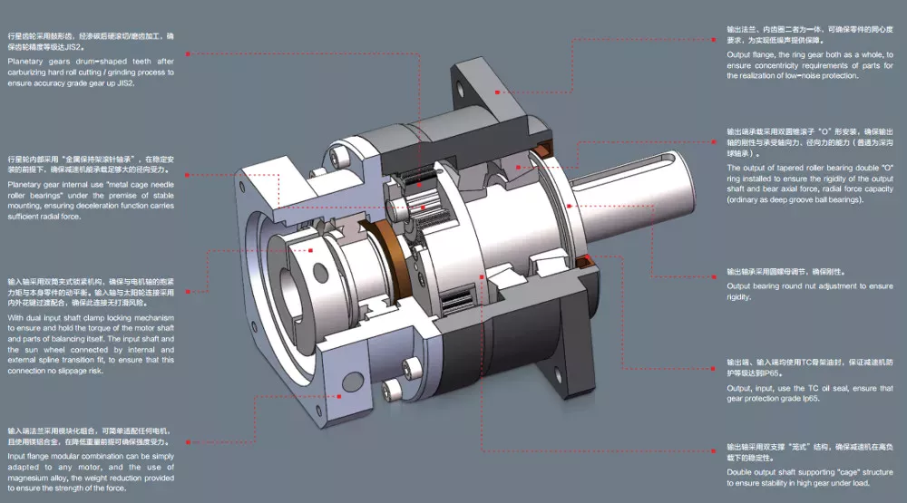
Planetary gearboxes with carrier
A planetary gearbox is a type of gearbox with three or more stages. They have a sun gear, which is usually the input gear, and planet gears, also called the outer gears. The carrier that connects the planet gears to the output shaft is called a ring gear. A planetary gearbox is generally designed to meet specific application and environmental requirements, but there are some factors to consider when choosing one.
The compact footprint of planetary gear sets results in high heat dissipation. This can be a problem in applications with sustained performance or high speeds. As a result, planetary gear sets often include lubricants, which present a cooling effect while also reducing noise and vibration. Some planetary gears even feature a carrier to make the installation process easier. Here are some things to keep in mind when choosing a planetary gear set.
Planetary gearboxes with carrier have several advantages over other types of gearboxes. Unlike conventional gearboxes, planetary gears have a common central shaft, and the tangential forces between the gears cancel out at the center of the ring gear. Because of this, planetary gearboxes are commonly used in input/output applications, and their compact size allows for a wide range of gear reductions. These gears can also produce higher torque density.
Planetary gearboxes with traction
Planetary gears are similar to the planetary system, in that each pinion rotates around a sun gear. The output of the planetary gear unit is lower than the drive rotation speed, but the torque is higher. As the number of planet gear wheels increases, so does the torque. Planetary gear systems contain three to four planet gears, and each is in constant mesh with the others. Power applied to any one member rotates the entire assembly.
Typical applications for planetary gear sets include high-precision motion control. In these applications, high torque, torsional stiffness, and low backlash are required. Planetary gear sets are also ideal for motors with higher speeds. A number of factors contribute to the reliability of these devices. The low backlash and large torque capacity of a planetary gear motor allow them to be used in a wide range of applications.
Planetary gearboxes with electric motors
If you’re in the market for a new gearbox, you may have already heard about planetary gearboxes. The planetary gearbox is a high-efficiency, low-noise gearbox. CZPT manufactures high-torque planetary gearboxes with low backlash. They also make economy planetary gearboxes for lower loads. However, with so many different types available, choosing the right one for your needs can be challenging.
These planetary gearboxes are a compact alternative to conventional pinion-and-gear reducers. They offer high-speed reduction and high torque transfer, and are often used for space-constrained applications. But before you can understand how they work, you’ll need to understand a little about their construction. There are a few things to look for that you may not have noticed before.
The most common type of planetary gearbox is a PM81/LN. It features a set of DC brush motors with diameter 77mm, a stator, and two or more outer gears. Each of these gears is connected to an output shaft through a carrier. They can also be used with brakes, encoders, or a clutch. A planetary gearbox is one of the most reliable gearbox types on the market.
Planetary gearboxes with hydraulic motors
A planetary gearbox is a combination of two gears, the sun and the planets. The sun gear rotates at high speed, while the planets roll around and orbit around the ring gear. The output shaft has the same direction of rotation as the input shaft. The benefits of a planetary gearbox include high reduction ratios, efficiency, space-saving compactness, and higher overload capacity. These gears are also more stable and compact, and they do not suffer from self-locking properties.
Planetary gearboxes are a highly efficient way to power hydraulic lifts. They can be input via electric, hydraulic, or air motors. The drive arrangement can be mounted on a bare shaft, splined shaft, or a parallel keyed input shaft. Depending on the application, bespoke gearboxes can be manufactured with a variety of features and functions.
Planetary gearboxes with combustion engines
There are many different applications of planetary gear sets. The most common is the distribution of power between two wheels in a car’s drive axle. Four-wheel drives use two axle differentials, which are further augmented by a centre differential. Hybrid electric vehicles use summation gearboxes to distribute power from the combustion engine to the wheels and to an electric motor. Planetary gear sets also combine the two different types of motors to form one hybrid vehicle.
To understand how planetary gear sets work, it is important to understand the underlying mechanical principles. For example, Fig. 4.6 shows a stick diagram illustrating two planetary gear sets connected by a lever. The two levers are the same length, so the system is analogous to a single lever. When calculating the torque, it is essential to consider the lever diagram. Similarly, if two gear sets are connected by vertical links, the horizontal links must be horizontal.
editor by CX 2023-04-23
China Planetary Gear Reducer Standard Industrial Gearbox S98 Series Gearbox Reduction Gear Motor calculate gear ratio planetary gearbox
Solution Description
Solution Description
Merchandise Description
-S Series Helical gearbox
Merchandise Attributes
1.Substantial modular design.
2.Integrated casting housing,compact dimension,high loading support, secure transmitting and reduced sound degree.
3.With the particular gear geometry, it receives substantial torque, efficiency and lengthy daily life circle.
four.It can obtain the direct mixture for 2 sets of gearbox.
5.Large efficiency and save energy.
6.Preserve cost and reduced upkeep.
Product Parameters
one. Technical data
| Size | 38 | 48 | 58 | sixty eight | seventy eight | 88 | 98 |
| Framework | BS BSA BSF BSAF BSAT BSAZ | ||||||
| Input Power(kW) | .18~.75 | .eighteen~1.5 | .eighteen~3 | .twenty five~5.five | .fifty five~7.5 | .seventy five~15 | 1.5~22 |
| Ratio | 10.27~a hundred sixty five.seventy one | 11.46~244.74 | 10.seventy eight~196.21 | 11.fifty five~227.twenty | 9.ninety six~241.09 | 11.83~223.26 | 12.seventy five~230.48 |
| Permissible Torque(N.m) | ninety | 170 | three hundred | 520 | 1270 | 2280 | 4000 |
| Excess weight(kg) | 7 | 10 | fourteen | 26 | fifty | one hundred | a hundred and seventy |
two: Design alternative
| S series gear units are available in the following designs | |
| S…Y… | Foot-mounted parallel shaft helical gear units with solid shaft |
| SA…Y… | Parallel shaft helical gear units with hollow shaft |
| SAZ…Y… | Quick-flange mounted parallel shaft helical gear units with hollow shaft |
| SF…Y… | Flange-mounted parallel shaft helical gear units with solid shaft |
| SAT…Y… | Flange-mounted parallel shaft helical gear units with hollow shaft |
| S(SF,SA,SAF,SAZ)S… | Shaft input parallel shaft helical gear units |
| S(SF,SA,SAF,SAZ)…R…Y… | Combinatorial parallel shaft helical gear units |
| S(SF,SA,SAF,SAZ)S…R… | Shaft input combinatorial parallel shaft helical gear units |
Resources Knowledge Sheet
|
Housing content |
Grey Cast iron |
|
Housing hardness |
HBS163~255 |
|
Gear content |
20CrMnTi alloy steel |
|
Floor hardness of gears |
HRC58°~62 ° |
|
Gear main hardness |
HRC33~forty eight |
|
Input / Output shaft content |
40Cr alloy metal |
|
Enter / Output shaft hardness |
HRC32~36 |
|
Machining precision of gears |
accurate grinding, 6~5 Quality |
|
Lubricating oil |
GB L-CKC220-460, Shell Omala220-460 |
|
Heat treatment |
tempering, cementiting, quenching, normalizing, and many others. |
|
Efficiency |
ninety four%~ninety six% (is dependent on the transmission stage) |
|
Sound (MAX) |
60~68dB |
|
Temp. rise (MAX) |
40°C |
|
Temp. rise (Oil)(MAX) |
50°C |
|
Vibration |
≤20µm |
|
Backlash |
≤20Arcmin |
|
Brand of bearings |
China top brand bearing, HRB/LYC/ZWZ/C&U. Or other brands asked for, SKF, FAG, INA, NSK. |
|
Model of oil seal |
NAK — ZheJiang or other brand names requested |
In depth Photos
Our procedure of generation
Our item line
Organization Profile
Organization Profile
Bode was started in 2007, which is found in HangZhou metropolis, ZHangZhoug province. As 1 specialist producer and exporter, we have more than 17 years’ knowledge in R & D of worm reducer, equipment reducer, gearbox , AC motor and relative spare parts. We have manufacturing facility with sophisticated manufacturing and check tools, the strong development of crew and generating ability provide our customers with large top quality products. Our products broadly served to numerous industries of Metallurgy, Chemicals, lifting, mining, Petroleum, textile, medication, wooden and many others. Main marketplaces: China, Africa, Australia, Vietnam, Turkey, Japan, Korea, Philippines… Welcome to question us any queries, excellent offer often for you for extended expression organization.
FAQ
Q1: Are you buying and selling business or producer?
A: We are manufacturing facility.
Q2: What types of gearbox can you create for us?
A: Primary merchandise of our company: R, S, K, F sequence helical-tooth reducer, RV sequence worm gear reducer,H Collection Parallel Shaft Helical Reduction Gear Box
Q3: Can you make as per personalized drawing?
A: Of course, we provide custom-made service for clients.
This fall: Can we get 1 pc of every merchandise for high quality screening?
A: Yes, we are glad to accept demo order for quality testing.
Q5: What data shall we give before inserting a purchase order?
A: a) Sort of the gearbox, ratio, input and output type, input flange, mounting placement, and motor informationetc.
b) Housing coloration.
c) Obtain quantity.
d) Other particular requirements.
Q6: How long is your supply time?
A: Normally it is 5-ten days if the items are in inventory. or it is 15-twenty days if the goods are not in inventory.
Q7: What is your terms of payment ?
A: 30% Advance payment by T/T soon after signing the contract.70% prior to delivery
If you are intrigued in our item, welcome to get in touch with with us.
Our team will do our very best to meet up with your need to have 🙂
|
/ Piece | |
1 Piece (Min. Order) |
###
| Application: | Motor, Machinery, Marine, Agricultural Machinery |
|---|---|
| Function: | Distribution Power, Change Drive Torque, Speed Changing, Speed Reduction |
| Layout: | Coaxial |
| Hardness: | Hardened Tooth Surface |
| Installation: | Horizontal Type |
| Step: | Double-Step |
###
| Samples: |
US$ 90/Piece
1 Piece(Min.Order) |
|---|
###
| Customization: |
|---|
###
| Size | 38 | 48 | 58 | 68 | 78 | 88 | 98 |
| Structure | BS BSA BSF BSAF BSAT BSAZ | ||||||
| Input Power(kW) | 0.18~0.75 | 0.18~1.5 | 0.18~3 | 0.25~5.5 | 0.55~7.5 | 0.75~15 | 1.5~22 |
| Ratio | 10.27~165.71 | 11.46~244.74 | 10.78~196.21 | 11.55~227.20 | 9.96~241.09 | 11.83~223.26 | 12.75~230.48 |
| Permissible Torque(N.m) | 90 | 170 | 300 | 520 | 1270 | 2280 | 4000 |
| Weight(kg) | 7 | 10 | 14 | 26 | 50 | 100 | 170 |
###
| S series gear units are available in the following designs | |
| S…Y… | Foot-mounted parallel shaft helical gear units with solid shaft |
| SA…Y… | Parallel shaft helical gear units with hollow shaft |
| SAZ…Y… | Short-flange mounted parallel shaft helical gear units with hollow shaft |
| SF…Y… | Flange-mounted parallel shaft helical gear units with solid shaft |
| SAT…Y… | Flange-mounted parallel shaft helical gear units with hollow shaft |
| S(SF,SA,SAF,SAZ)S… | Shaft input parallel shaft helical gear units |
| S(SF,SA,SAF,SAZ)…R…Y… | Combinatorial parallel shaft helical gear units |
| S(SF,SA,SAF,SAZ)S…R… | Shaft input combinatorial parallel shaft helical gear units |
###
|
Housing material
|
Grey Cast iron
|
|
Housing hardness
|
HBS163~255
|
|
Gear material
|
20CrMnTi alloy steel
|
|
Surface hardness of gears
|
HRC58°~62 °
|
|
Gear core hardness
|
HRC33~48
|
|
Input / Output shaft material
|
40Cr alloy steel
|
|
Input / Output shaft hardness
|
HRC32~36
|
|
Machining precision of gears
|
accurate grinding, 6~5 Grade
|
|
Lubricating oil
|
GB L-CKC220-460, Shell Omala220-460
|
|
Heat treatment
|
tempering, cementiting, quenching, normalizing, etc.
|
|
Efficiency
|
94%~96% (depends on the transmission stage)
|
|
Noise (MAX)
|
60~68dB
|
|
Temp. rise (MAX)
|
40°C
|
|
Temp. rise (Oil)(MAX)
|
50°C
|
|
Vibration
|
≤20µm
|
|
Backlash
|
≤20Arcmin
|
|
Brand of bearings
|
China top brand bearing, HRB/LYC/ZWZ/C&U. Or other brands requested, SKF, FAG, INA, NSK.
|
|
Brand of oil seal
|
NAK — Taiwan or other brands requested
|
|
/ Piece | |
1 Piece (Min. Order) |
###
| Application: | Motor, Machinery, Marine, Agricultural Machinery |
|---|---|
| Function: | Distribution Power, Change Drive Torque, Speed Changing, Speed Reduction |
| Layout: | Coaxial |
| Hardness: | Hardened Tooth Surface |
| Installation: | Horizontal Type |
| Step: | Double-Step |
###
| Samples: |
US$ 90/Piece
1 Piece(Min.Order) |
|---|
###
| Customization: |
|---|
###
| Size | 38 | 48 | 58 | 68 | 78 | 88 | 98 |
| Structure | BS BSA BSF BSAF BSAT BSAZ | ||||||
| Input Power(kW) | 0.18~0.75 | 0.18~1.5 | 0.18~3 | 0.25~5.5 | 0.55~7.5 | 0.75~15 | 1.5~22 |
| Ratio | 10.27~165.71 | 11.46~244.74 | 10.78~196.21 | 11.55~227.20 | 9.96~241.09 | 11.83~223.26 | 12.75~230.48 |
| Permissible Torque(N.m) | 90 | 170 | 300 | 520 | 1270 | 2280 | 4000 |
| Weight(kg) | 7 | 10 | 14 | 26 | 50 | 100 | 170 |
###
| S series gear units are available in the following designs | |
| S…Y… | Foot-mounted parallel shaft helical gear units with solid shaft |
| SA…Y… | Parallel shaft helical gear units with hollow shaft |
| SAZ…Y… | Short-flange mounted parallel shaft helical gear units with hollow shaft |
| SF…Y… | Flange-mounted parallel shaft helical gear units with solid shaft |
| SAT…Y… | Flange-mounted parallel shaft helical gear units with hollow shaft |
| S(SF,SA,SAF,SAZ)S… | Shaft input parallel shaft helical gear units |
| S(SF,SA,SAF,SAZ)…R…Y… | Combinatorial parallel shaft helical gear units |
| S(SF,SA,SAF,SAZ)S…R… | Shaft input combinatorial parallel shaft helical gear units |
###
|
Housing material
|
Grey Cast iron
|
|
Housing hardness
|
HBS163~255
|
|
Gear material
|
20CrMnTi alloy steel
|
|
Surface hardness of gears
|
HRC58°~62 °
|
|
Gear core hardness
|
HRC33~48
|
|
Input / Output shaft material
|
40Cr alloy steel
|
|
Input / Output shaft hardness
|
HRC32~36
|
|
Machining precision of gears
|
accurate grinding, 6~5 Grade
|
|
Lubricating oil
|
GB L-CKC220-460, Shell Omala220-460
|
|
Heat treatment
|
tempering, cementiting, quenching, normalizing, etc.
|
|
Efficiency
|
94%~96% (depends on the transmission stage)
|
|
Noise (MAX)
|
60~68dB
|
|
Temp. rise (MAX)
|
40°C
|
|
Temp. rise (Oil)(MAX)
|
50°C
|
|
Vibration
|
≤20µm
|
|
Backlash
|
≤20Arcmin
|
|
Brand of bearings
|
China top brand bearing, HRB/LYC/ZWZ/C&U. Or other brands requested, SKF, FAG, INA, NSK.
|
|
Brand of oil seal
|
NAK — Taiwan or other brands requested
|
A Brief Overview of the Spur Gear and the Helical Planetary Gearbox
This article will provide a brief overview of the Spur gear and the helical planetary gearbox. To learn more about the advantages of these gearboxes, read on. Here are a few common uses for planetary gears. A planetary gearbox is used in many vehicles. Its efficiency makes it a popular choice for small engines. Here are three examples. Each has its benefits and drawbacks. Let’s explore each one.
helical planetary gearbox
In terms of price, the CZPT is an entry-level, highly reliable helical planetary gearbox. It is suitable for applications where space, weight, and torque reduction are of high concern. On the other hand, the X-Treme series is suitable for applications requiring high-acceleration, high-axial and radial loads, and high-speed performance. This article will discuss the benefits of each type of planetary gearbox.
A planetary gearbox’s traction-based design is a variation of the stepped-planet design. This variation relies on the compression of the elements of the stepped-planet design. The resulting design avoids restrictive assembly conditions and timing marks. Compared to conventional gearboxes, compound planetary gears have a greater transmission ratio, and they do so with an equal or smaller volume. For example, a 2:1 ratio compound planet would be used with a 50-ton ring gear, and the result would be the same as a 100-ton ring gear, but the planetary disks would be half the diameter.
The Helical planetary gearbox uses three components: an input, an output, and a stationary position. The basic model is highly efficient and transmits 97% of the input power. There are three main types of planetary gearboxes, each focusing on a different performance characteristic. The CZPT basic line is an excellent place to start your research into planetary gearboxes. In addition to its efficiency and versatility, this gearbox has a host of modular features.
The Helical planetary gearbox has multiple advantages. It is versatile, lightweight, and easy to maintain. Its structure combines a sun gear and a planet gear. Its teeth are arranged in a way that they mesh with each other and the sun gear. It can also be used for stationary applications. The sun gear holds the carrier stationary and rotates at the rate of -24/16 and -3/2, depending on the number of teeth on each gear.
A helical planetary gearbox can reduce noise. Its shape is also smaller, reducing the size of the system. The helical gears are generally quieter and run more smoothly. The zero helix-angle gears, in contrast, have smaller sizes and higher torque density. This is a benefit, but the latter also increases the life of the system and is less expensive. So, while the helical planetary gearbox has many advantages, the latter is recommended when space is limited.
The helical gearbox is more efficient than the spur gear, which is limited by its lack of axial load component. The helical gears, on the other hand, generate significant axial forces in the gear mesh. They also exhibit more sliding at the points of tooth contact, adding friction forces. As such, the Helical planetary gearbox is the preferred choice in servo applications. If you’re looking for a gearbox to reduce noise and improve efficiency, Helical planetary gearboxes are the right choice.
The main differences between the two types of planetary gears can be found in the design of the two outer rings. The outer ring is also called the sun gear. The two gears mesh together according to their own axes. The outer ring is the planetary gear’s carrier. Its weight is proportional to the portion of the ring that is stationary. The carrier sets the gaps between the two gears.
Helical gears have angled teeth and are ideal for applications with high loads. They are also extremely durable and can transfer a high load. A typical Helical gearbox has two pairs of teeth, and this ensures smooth transmission. In addition, the increased contact ratio leads to lower fluctuations in mesh stiffness, which means more load capacity. In terms of price, Helical planetary gears are the most affordable gearbox type.
The outer ring gear drives the inner ring gear and surrounding planetary parts. A wheel drive planetary gearbox may have as much as 332,000 N.m. torque. Another common type of planetary gearbox is wheel drive. It is similar to a hub, but the outer ring gear drives the wheels and the sun gear. They are often combined over a housing to maximize size. One-stage Helical gears can be used in bicycles, while a two-stage planetary gear system can handle up to 113,000 N.m. torque.
The design of a helical planetary geartrain is complicated. It must comply with several constraints. These constraints relate to the geometrical relationship of the planetary geartrains. This study of the possible design space of a Helical geartrain uses geometric layouts. The ring gear, sun, and ring gear have no effect on the ratio of the planetary transmission. Nonetheless, helical geartrains are a good choice for many applications.
Spur gear planetary gearbox
The combination of planetary gears and spur gears in a transmission system is called a planetary or spur gearbox. Both the planetary gear and spur gear have their own characteristics and are used in various kinds of vehicles. They work in a similar way, but are built differently. Here are some important differences between the two types of gears. Listed below are some of the most important differences between them:
Helical gears: As opposed to spur gears, helical gears generate significant axial forces in the gear mesh. They also feature greater sliding contact at the point of tooth contact. The helix angle of a gearbox is generally in the range of 15 to 30 degrees. The higher the helix angle, the more axial forces will be transmitted. The axial force in a helical gearbox is greater than that of a spur gear, which is the reason why helical gears are more efficient.
As you can see, the planetary gearhead has many variations and applications. However, you should take care in selecting the number of teeth for your planetary gear system. A five:1 spur gear drive ratio, for example, means that the sun gear needs to complete five revolutions for every output carrier revolution. To achieve this, you’ll want to select a sun gear with 24 teeth, or five mm for each revolution. You’ll need to know the metric units of the planetary gearhead for it to be compatible with different types of machines.
Another important feature of a planetary gearbox is that it doesn’t require all of the spur gears to rotate around the axis of the drive shaft. Instead, the spur gears’ internal teeth are fixed and the drive shaft is in the same direction as the output shaft. If you choose a planetary gearbox with fixed internal teeth, you’ll need to make sure that it has enough lubrication.
The other significant difference between a spur gear and a planetary gearbox is the pitch. A planetary gearbox has a high pitch diameter, while a spur gear has low pitch. A spur gear is able to handle higher torques, but isn’t as efficient. In addition, its higher torque capability is a big drawback. Its efficiency is similar to that of a spur gear, but it is much less noisy.
Another difference between planetary and spur gear motors is their cost. Planetary gear motors tend to be more expensive than spur gear motors. But spur gears are cheaper to produce, as the gears themselves are smaller and simpler. However, planetary gear motors are more efficient and powerful. They can handle lower torque applications. But each gear carries a fixed load, limiting their torque. A spur gear motor also has fewer internal frictions, so it is often suited for lower torque applications.
Another difference between spur gears and planetary gears is their orientation. Single spur gears are not coaxial gearboxes, so they’re not coaxial. On the other hand, a planetary gearbox is coaxial, meaning its input shaft is also coaxial. In addition to this, a planetary gearbox is made of two sets of gear wheels with the same orientation. This gives it the ability to achieve concentricity.
Another difference between spur gears and planetary gears is that a planetary gear has an integer number of teeth. This is important because each gear must mesh with a sun gear or a ring gear. Moreover, each planet must have a corresponding number of teeth. For each planet to mesh with the sun, the teeth must have a certain distance apart from the other. The spacing between planets also matters.
Besides the size, the planetary gear system is also known as epicyclic gearing. A planetary gear system has a sun gear in the center, which serves as the input gear. This gear has at least three driven gears. These gears engage with each other from the inside and form an internal spur gear design. These gear sets are highly durable and able to change ratios. If desired, a planetary gear train can be converted to another ratio, thereby enhancing its efficiency.
Another important difference between a spur gear and a planetary gearbox is the type of teeth. A spur gear has teeth that are parallel to the shaft, while a planetary gear has teeth that are angled. This type of gear is most suitable for low-speed applications, where torque is necessary to move the actuation object. Spur gears also produce noise and can damage gear teeth due to repeated collisions. A spur gear can also slip, preventing torque from reaching the actuation object.
editor by CX 2023-03-28