Product Description
Custom Large Output Torque Worm Reducer Gear Box Reducer Accessories
ZHangZhoug Xiafeng Precision Die Casting Co., Ltd., we specialize in the design, development, production, and sales of pump accessories, valve accessories, amusement park accessories, gas station accessories, aluminum die casting, aluminum metal crafts, electric vehicle accessories, pneumatic actuator accessories, gearbox gears, gearbox housings, primary gears, infinite gears, machine base shells, stepless speed control covers, and aluminum machine base.
Product Description
Gearbox Castings
Our Worm gearbox reducer has many items for your choosing and we can produce as per your drawing or sample to meet your special request
We can also supply Gearbox, agricultural gearbox, planetary gearbox, worm gearbox, CHINAMFG gearbox, marine gearbox, gearbox, reduction gearbox, transmission gearbox, gearbox, mower gearbox, rotary cutter gearbox, small transmission gearbox, gearbox for conveyor, bevel gearbox, helical gearbox, swing gearbox, variable speed gearbox, differential gearbox, small planetary gearbox, reducer gearbox, tiller gearbox, pto gearbox, gearbox reducer, hollow shaft gearbox, speed reduction gearbox, industrial gearbox, planetary reduction gearbox, lawn mower gearbox, rotary tiller gearbox, gearbox transmission, worm reduction gearbox, aluminum gearbox, forklift gearbox, nmrv 075 worm gearbox, nmrv030 worm gearbox, shaft mounted gearbox, nmrv 050 worm gearbox, gearbox for agricultural machinery, power tiller gearbox, manual worm gearbox, spiral bevel gearbox, nmrv gearbox, worm wheel gearbox, reduce speed gearbox, industrial transmission gearbox, worm reducer gearbox, gearbox rpm reducer, helical gearbox reducer, wheel planetary gearbox, nmrv040 worm gearbox, worm gearbox reducer, nmrv worm gearbox, aluminium worm gearbox, gearbox reduction, rv series worm gearbox, worm speed gearbox, nmrv050 worm gearbox, gear reducer, worm gear reducer, helical gear reducer, gear speed reducer, worm gear speed reducer, shaft mounted gear reducer, planetary gear reducer, helical gear speed reducer, worm CHINAMFG reducer, speed gear reducer, bevel gear reducer, planetary gear speed reducer, spur gear reducer, aluminum worm gear reduce, nmrv worm gear reducers, helical-worm gear reducer, helical bevel gear reducers, high speed gear reducer, gear speed reducers, industrial gear reducer, high torque gear reducer
1. Large output torque
2. Safe, reliable, economical and durable
3. Stable transmission, quiet operation
4. High carrying ability
5. High modularization design, may equip with various outer power input conveniently. Same machine type may equip with various power motor. It is easy to realize the combination and junction between every machine type
6. Transmission ratio: Fine division, wide scope. The combined machine type may form very large transmission ratio, i. E. Output very low rotary speed.
7. Form of installation: The position to be installed is not limited.
8. High strength, compact the box body of high strength cast iron, gear and gear shaft adapts the gas carbonization, quenching and fine grinding process, therefore the bearing capacity of unit volume is high.
9. Long life: Under the condition of correct type chosen(including choosing suitable operation parament ) normal operation and maintenance, the life if main parts speed reducer(except wearing parts)should not be less than 20000 hours. The wearing parts include lubricating oil, oil seal and bearing.
10. Low noise: Because main parts of speed reducer are processed, and tested critically, therefore the noise of speed reducer is low.
11. Parallel axis-bevel wheel speed-down motor.
See the below features:
Size: 40mm—160mm
Reduction ratio: 3 — 512
Torque transmission: 5 Nm — 8 95 Nm
Precision backlash: ≤ 5arcmin
Running noise: 51 70 dB (A)
Product Parameters
| Name | G reducer |
| Material | Aluminum Alloy |
| Brand | ZHangZhoug Xiaofeng |
| Product model | G18/G22/G28/G32 |
| Application | Construction equipment/mechanical equipment, etc |
Detailed Photos
Feature
Application
Company Profile
ZHangZhoug Xiafeng Precision Die Casting Co., Ltd. is a company located in Oubei, HangZhoua, HangZhou, known as the “hometown of pumps and valves”. We specialize in the design, development, production, and sales of pump accessories, valve accessories, amusement park accessories, gas station accessories, aluminum die casting, aluminum metal crafts, electric vehicle accessories, pneumatic actuator accessories, gearbox gears, gearbox housings, primary gears, infinite gears, machine base shells, stepless speed control covers, and aluminum machine base.
FAQ
Q1 : Could I put my own logo on it?
A : Sure, We accept OEM and ODM.
Q2 : What is your sample policy?
A : We can supply the sample, but the customers have to pay the shipping cost.
Q3 : Could I produce according to the samples?
A : Of course. we can produce by your samples or technical drawing, We can build the molds.
Q4 : How long is production time?
A : Based on the quantities sample order 7-15 days, mass order 30-60days.
Q5 : Do you test all your goods before delivery?
A : Of course, We have 100% test before delivery.
/* January 22, 2571 19:08:37 */!function(){function s(e,r){var a,o={};try{e&&e.split(“,”).forEach(function(e,t){e&&(a=e.match(/(.*?):(.*)$/))&&1
| Application: | Motor, Electric Cars, Motorcycle, Machinery, Marine, Toy, Agricultural Machinery, Car, Construction Equipment/Mechanical Equipm |
|---|---|
| Hardness: | Hardened Tooth Surface |
| Installation: | Horizontal Type |
| Layout: | Coaxial |
| Gear Shape: | Conical – Cylindrical Gear |
| Step: | Double-Step |
| Samples: |
US$ 100/Piece
1 Piece(Min.Order) | |
|---|
| Customization: |
Available
|
|
|---|

How does the choice of winch drives affect the overall performance and reliability of lifting operations?
The choice of winch drives has a significant impact on the overall performance and reliability of lifting operations. Here’s a detailed explanation of how the choice of winch drives affects performance and reliability:
- Lifting Capacity:
The choice of winch drives directly affects the lifting capacity of the system. Different winch drives have varying load capacities, and selecting an appropriate winch drive that matches the intended lifting requirements is crucial. Choosing a winch drive with insufficient lifting capacity can result in overloading, which can lead to equipment failure, safety hazards, and potential damage to the load or surrounding structures. On the other hand, selecting a winch drive with a higher lifting capacity than necessary can lead to unnecessary costs and inefficient operation. Therefore, selecting the right winch drive with the appropriate lifting capacity is essential for optimal performance and reliability.
- Speed and Control:
The choice of winch drives also affects the speed and control of lifting operations. Different winch drives offer varying speed ranges and control options. High-quality winch drives provide smooth and precise speed control, allowing for accurate positioning and delicate handling of loads. The choice of winch drives with suitable speed and control capabilities ensures efficient and controlled lifting operations, reducing the risk of accidents, damage to the load, or strain on the lifting equipment. Additionally, winch drives with advanced control features, such as programmable logic controllers (PLCs) or electronic control systems, enhance operational reliability and performance by enabling synchronized movements and automation.
- Durability and Reliability:
The choice of winch drives significantly impacts the durability and reliability of lifting operations. High-quality winch drives constructed with robust materials and designed for heavy-duty applications offer enhanced durability and reliability. They can withstand the demanding conditions and stress associated with lifting operations, minimizing the risk of breakdowns, malfunctions, or premature wear. Choosing winch drives from reputable manufacturers known for their quality and reliability ensures long-term performance and reduces the need for frequent maintenance or replacement, enhancing the overall reliability of the lifting operations.
- Safety Features:
Winch drives come with various safety features that contribute to the overall performance and reliability of lifting operations. These safety features include overload protection systems, emergency stop controls, limit switches, and fail-safe mechanisms. The choice of winch drives with comprehensive safety features enhances the safety of lifting operations by preventing overloading, safeguarding against equipment failures, and providing emergency shutdown options in critical situations. Properly selecting winch drives with appropriate safety features ensures compliance with safety regulations, reduces the risk of accidents, and enhances the reliability of lifting operations.
- Compatibility and Integration:
Choosing winch drives that are compatible with the overall lifting system and easily integrable with other components is crucial for optimal performance and reliability. Compatibility issues can arise if the selected winch drive does not match the mechanical requirements, power supply, or control interfaces of the lifting system. Incompatibility can lead to operational inefficiencies, increased maintenance needs, or even system failures. Therefore, careful consideration of the compatibility and integration aspects when choosing winch drives ensures seamless integration, smooth operation, and enhanced reliability of lifting operations.
In summary, the choice of winch drives significantly impacts the overall performance and reliability of lifting operations. Factors such as lifting capacity, speed and control capabilities, durability and reliability, safety features, and compatibility with the overall system should be carefully considered when selecting winch drives. By choosing the right winch drives that meet the specific requirements of the lifting operations, operators can achieve optimal performance, ensure safe and efficient lifting, and enhance the overall reliability of the operations.

How does the design of winch drives impact their performance in different environments?
The design of winch drives plays a critical role in determining their performance in different environments. Various design factors influence the reliability, efficiency, and adaptability of winch drives to specific operating conditions. Here’s a detailed explanation of how the design of winch drives impacts their performance:
- Load Capacity and Power:
The design of winch drives directly affects their load capacity and power capabilities. Factors such as motor size, gear ratio, and drum diameter determine the maximum load capacity a winch drive can handle. The power output of the motor and the mechanical advantage provided by the gear system impact the winch drive’s ability to lift or pull heavy loads effectively. A well-designed winch drive with appropriate load capacity and power ensures optimal performance in different environments.
- Speed and Control:
The design of winch drives influences their speed and control characteristics. The gear ratio and motor specifications determine the speed at which the winch drive can operate. Additionally, the presence of a variable speed control mechanism allows for precise and controlled movement of loads. The design should strike a balance between speed and control, depending on the specific application and operational requirements in different environments.
- Drive System:
Winch drives can utilize different drive systems, such as electric, hydraulic, or pneumatic. The design of the drive system impacts the performance of the winch drive in different environments. Electric winch drives are commonly used due to their ease of use, precise control, and suitability for various applications. Hydraulic winch drives offer high power output and are often preferred in heavy-duty applications. Pneumatic winch drives are suitable for environments where electricity or hydraulics are not readily available. The design should align with the specific requirements and constraints of the environment in which the winch drive will be used.
- Enclosure and Protection:
The design of the winch drive enclosure and protection features significantly impacts its performance in different environments. Winch drives used in outdoor or harsh environments should have robust enclosures that provide protection against dust, moisture, and other contaminants. Sealed or weatherproof enclosures prevent damage to internal components and ensure reliable operation. Additionally, features such as thermal protection and overload protection are designed to safeguard the winch drive from overheating or excessive strain, enhancing its performance and longevity.
- Mounting and Installation:
The design of winch drives should consider the ease of mounting and installation. Mounting options such as bolt-on, weld-on, or integrated mounting plates offer flexibility for different installation scenarios. The design should also take into account the space constraints and mounting requirements of the specific environment. Easy and secure installation ensures proper alignment, stability, and efficient operation of the winch drive.
- Control and Safety Features:
The design of winch drives includes control and safety features that impact their performance in different environments. Control systems can range from simple push-button controls to advanced remote controls or integrated control panels. The design should provide intuitive and user-friendly control interfaces for efficient operation. Safety features such as emergency stop mechanisms, load limiters, and overload protection are crucial to prevent accidents and ensure safe operation in various environments. The design should prioritize the incorporation of appropriate safety features based on the specific application and environmental conditions.
By considering these design factors, winch drives can be optimized for performance, reliability, and safety in different environments. A well-designed winch drive that aligns with the specific requirements of the environment will deliver efficient and effective lifting or pulling capabilities while ensuring long-term durability and functionality.

How does the design of a winch drive contribute to efficient load lifting and pulling?
The design of a winch drive plays a critical role in ensuring efficient load lifting and pulling operations. Various design considerations are implemented to optimize performance, reliability, and safety. Here’s a detailed explanation of how the design of a winch drive contributes to efficient load lifting and pulling:
- Power and Torque:
A well-designed winch drive is equipped with a power source and gearbox that provide sufficient power and torque to handle the intended load. The power source, whether it’s an electric motor or hydraulic system, should have adequate capacity to generate the required energy for the pulling or lifting operation. The gearbox or transmission is designed to provide the appropriate torque output, matching the load requirements. By ensuring the winch drive has the necessary power and torque, it can efficiently handle the load without straining the components or compromising performance.
- Gearing and Speed Control:
The gearing system within the winch drive allows for precise control over the speed of the pulling or lifting operation. The gearbox is designed with different gear ratios, enabling the operator to select the desired speed based on the specific requirements of the task. This capability is crucial for efficient load handling. For instance, a higher gear ratio can be used for lighter loads or faster pulling speeds, while a lower gear ratio provides increased pulling power for heavier loads. The ability to control the speed optimizes the efficiency of the winch drive by adapting to the load characteristics and operational needs.
- Drum Size and Cable Capacity:
The design of the winch drive includes considerations for the drum size and cable capacity. The drum is responsible for winding or unwinding the cable during the pulling or lifting operation. A larger drum diameter allows for a greater length of cable to be wound, which increases the pulling capacity of the winch. The drum design should also ensure proper cable alignment and smooth winding to prevent cable damage or entanglement. By optimizing the drum size and cable capacity, the winch drive can efficiently handle the load and accommodate the necessary cable length required for the task.
- Braking System:
An efficient winch drive incorporates a reliable braking system. The braking system is designed to hold the load securely when the winch is not actively pulling or lifting. It prevents the load from slipping or releasing unintentionally, ensuring safety and stability during operation. The braking system should engage quickly and provide sufficient holding force, even in the event of power loss or sudden load changes. A well-designed braking system contributes to the efficiency of load lifting and pulling by maintaining control and preventing accidents or damage.
- Control System and Safety Features:
The design of the winch drive includes a control system with intuitive controls and safety features. The control system allows the operator to manage the operation of the winch drive, including start/stop functions, direction control, and speed adjustment. Clear and user-friendly controls enhance operational efficiency and facilitate precise load handling. Additionally, safety features such as overload protection, emergency stop mechanisms, and limit switches are integrated into the winch drive design to ensure safe operation and prevent damage to the equipment or injury to personnel.
By considering power and torque requirements, gearing and speed control, drum size and cable capacity, braking systems, control systems, and safety features, the design of a winch drive contributes to efficient load lifting and pulling. These design elements work together to optimize performance, control, and safety, allowing the winch drive to handle loads effectively and reliably in various applications and industries.


editor by CX 2024-03-05
China Standard Worm Reduction Gear Box Speed Reducer Jack Worm Agricultural Planetary Helical Bevel Worm Steering Gear Drive Motor High Speed Nmrv Gearbox Reducer Manufacture
Product Description
Worm Reduction Gear Box Speed Reducer Jack Worm Agricultural Planetary Helical Bevel Worm Steering Gear Drive Motor High Speed Nmrv Gearbox Reducer Manufacture
Application of Nmrv Gearbox
NMRV gearboxes are a type of worm gear reducer that is used in a wide variety of applications. They are characterized by their compact size, high efficiency, and low noise. NMRV gearboxes are typically used in applications where high torque and low speed are required, such as:
- Conveyors: NMRV gearboxes are used in conveyors to transmit power from the motor to the conveyor belt. This allows the conveyor belt to move at a controlled speed and torque.
- Machine tools: NMRV gearboxes are used in machine tools to transmit power from the motor to the cutting tool. This allows the cutting tool to operate at a high speed and torque, which is necessary for cutting through tough materials.
- Wind turbines: NMRV gearboxes are used in wind turbines to transmit power from the blades to the generator. This allows the generator to generate electricity at a controlled speed and torque, which is necessary for providing power to homes and businesses.
- Robotics: NMRV gearboxes are used in robotics to transmit power from the motor to the robot’s joints. This allows the robot to move its joints at a controlled speed and torque, which is necessary for performing tasks such as picking and placing objects.
NMRV gearboxes are a versatile type of gear reducer that can be used in a wide variety of applications. They offer a number of advantages that can help to improve safety, efficiency, and productivity.
Here are some of the advantages of using NMRV gearboxes:
- Compact size: NMRV gearboxes are typically compact and lightweight, making them easy to install and maintain.
- High efficiency: NMRV gearboxes are highly efficient, which can lead to a reduction in energy consumption and operating costs.
- Low noise: NMRV gearboxes operate at a low noise level, which can make them ideal for use in noise-sensitive applications.
- Durability: NMRV gearboxes are designed to be durable and can withstand harsh environments.
Overall, NMRV gearboxes are a valuable tool for a variety of applications. They offer a number of advantages that can help to improve safety, efficiency, and productivity.
/* January 22, 2571 19:08:37 */!function(){function s(e,r){var a,o={};try{e&&e.split(“,”).forEach(function(e,t){e&&(a=e.match(/(.*?):(.*)$/))&&1
| Application: | Motor, Electric Cars, Motorcycle, Machinery, Marine, Agricultural Machinery, Car |
|---|---|
| Function: | Distribution Power, Clutch, Change Drive Torque, Change Drive Direction, Speed Changing, Speed Reduction, Speed Increase |
| Layout: | Coaxial |
| Hardness: | Hardened Tooth Surface |
| Installation: | Horizontal Type |
| Step: | Steel |
| Samples: |
US$ 9999/Piece
1 Piece(Min.Order) | |
|---|
How do winch drives contribute to the adaptability and versatility of mechanical systems in various settings?
Winch drives play a significant role in enhancing the adaptability and versatility of mechanical systems in various settings. Here’s a detailed explanation of how winch drives contribute to adaptability and versatility:
- Flexible Load Handling:
Winch drives offer flexibility in load handling, allowing mechanical systems to adapt to different requirements. They can handle a wide range of loads, from light to heavy, and provide precise control over the lifting, lowering, and positioning of loads. The ability to adjust the speed, torque, and direction of the winch drive enables it to accommodate different load characteristics and operational needs. This flexibility makes winch drives suitable for a variety of applications, including construction, manufacturing, marine, entertainment, and transportation industries.
- Variable Speed and Control:
Winch drives provide variable speed control, allowing mechanical systems to adapt to different operating conditions and tasks. The speed of the winch drive can be adjusted to match the specific requirements of the application, whether it involves slow and precise movements or fast and efficient operations. Additionally, winch drives offer precise control over acceleration, deceleration, and stopping, enabling smooth and controlled movements. This variable speed and control capability enhance the adaptability and versatility of mechanical systems in handling diverse tasks and operating in different environments.
- Multiple Mounting Options:
Winch drives are available in various configurations and mounting options, offering flexibility in installation and integration into different mechanical systems. They can be mounted horizontally, vertically, or at custom angles, depending on the specific requirements of the application. This versatility in mounting options allows winch drives to be easily incorporated into existing systems or adapted to fit space constraints in different settings. Whether it’s a stationary installation, mobile equipment, or overhead lifting system, winch drives can be positioned and mounted in a way that optimizes their functionality and adaptability.
- Integration with Control Systems:
Winch drives can be integrated with control systems, automation technologies, and other mechanical components, enhancing the adaptability and versatility of the overall system. They can be connected to programmable logic controllers (PLCs), human-machine interfaces (HMIs), or central control systems, enabling seamless integration and coordination with other equipment and processes. This integration allows for synchronized operations, centralized control, and automation of complex tasks, making the mechanical system more adaptable to changing requirements and versatile in different settings.
- Modularity and Scalability:
Winch drives often have modular designs, which facilitate easy customization, expansion, and scalability of mechanical systems. Additional winch drives can be added or existing ones can be reconfigured to accommodate changing load capacities or operational needs. This modularity allows mechanical systems to adapt to evolving requirements without significant redesign or replacement of the entire system. It provides the flexibility to scale up or down the capabilities of the system, making it versatile and adaptable to different settings and applications.
In summary, winch drives contribute to the adaptability and versatility of mechanical systems through their flexible load handling capabilities, variable speed and control, multiple mounting options, integration with control systems, and modularity. By incorporating winch drives, mechanical systems can adapt to different tasks, environments, and operational demands, making them versatile and suitable for a wide range of settings and applications.

How do winch drives contribute to precise and controlled movement in lifting operations?
Winch drives play a crucial role in achieving precise and controlled movement in lifting operations. They provide the necessary power and control to lift and lower loads in a controlled manner. Here’s a detailed explanation of how winch drives contribute to precise and controlled movement in lifting operations:
- Pulling Power:
Winch drives are designed to generate substantial pulling power, allowing them to lift heavy loads. The power output of the winch drive is determined by factors such as the type of drive (electric, hydraulic, or pneumatic), motor power, and gear ratios. The high pulling power of winch drives enables them to handle loads with precision and control, even in challenging lifting scenarios.
- Variable Speed Control:
Many winch drives offer variable speed control, allowing operators to adjust the lifting or lowering speed according to the specific requirements of the operation. This feature enables precise movement control, particularly when dealing with delicate or sensitive loads. Operators can slow down the speed for fine positioning or speed up the operation for more efficient lifting, depending on the situation. Variable speed control enhances the precision and control of the lifting process, minimizing the risk of load damage or accidents.
- Braking Systems:
Winch drives are typically equipped with braking systems to ensure load holding and prevent unintended movement. The braking systems are designed to engage when the winch motor is not actively pulling or lowering the load, effectively immobilizing the load at the desired position. This feature allows for precise control over the load’s movement and prevents it from unintentionally drifting or descending. The braking systems contribute to the overall safety and stability of the lifting operation.
- Control Mechanisms:
The control mechanisms of winch drives play a significant role in achieving precise and controlled movement. Winch drives can be operated manually, through remote control systems, or integrated control interfaces. Remote control systems, for example, enable operators to control the winch drive from a safe distance, providing better visibility and control over the lifting operation. Integrated control interfaces often offer additional features such as load monitoring, digital displays, and programmable settings, allowing for more precise and controlled movement of the load.
- Load Monitoring and Safety Features:
Winch drives may incorporate load monitoring systems and safety features to further enhance precise and controlled movement. Load monitoring systems provide real-time feedback on the load’s weight, allowing operators to adjust the lifting parameters accordingly. Safety features such as overload protection and limit switches prevent the winch drive from operating beyond its capacity or reaching unsafe positions, ensuring controlled movement and preventing damage or accidents.
By combining their pulling power, variable speed control, braking systems, control mechanisms, and safety features, winch drives enable precise and controlled movement in lifting operations. They provide the necessary power, control, and safety measures to handle heavy loads with accuracy, minimizing the risk of load damage, accidents, or injuries. The precise and controlled movement achieved through winch drives enhances operational efficiency, load positioning, and overall safety in lifting operations.
How does the design of a winch drive contribute to efficient load lifting and pulling?
The design of a winch drive plays a critical role in ensuring efficient load lifting and pulling operations. Various design considerations are implemented to optimize performance, reliability, and safety. Here’s a detailed explanation of how the design of a winch drive contributes to efficient load lifting and pulling:
- Power and Torque:
A well-designed winch drive is equipped with a power source and gearbox that provide sufficient power and torque to handle the intended load. The power source, whether it’s an electric motor or hydraulic system, should have adequate capacity to generate the required energy for the pulling or lifting operation. The gearbox or transmission is designed to provide the appropriate torque output, matching the load requirements. By ensuring the winch drive has the necessary power and torque, it can efficiently handle the load without straining the components or compromising performance.
- Gearing and Speed Control:
The gearing system within the winch drive allows for precise control over the speed of the pulling or lifting operation. The gearbox is designed with different gear ratios, enabling the operator to select the desired speed based on the specific requirements of the task. This capability is crucial for efficient load handling. For instance, a higher gear ratio can be used for lighter loads or faster pulling speeds, while a lower gear ratio provides increased pulling power for heavier loads. The ability to control the speed optimizes the efficiency of the winch drive by adapting to the load characteristics and operational needs.
- Drum Size and Cable Capacity:
The design of the winch drive includes considerations for the drum size and cable capacity. The drum is responsible for winding or unwinding the cable during the pulling or lifting operation. A larger drum diameter allows for a greater length of cable to be wound, which increases the pulling capacity of the winch. The drum design should also ensure proper cable alignment and smooth winding to prevent cable damage or entanglement. By optimizing the drum size and cable capacity, the winch drive can efficiently handle the load and accommodate the necessary cable length required for the task.
- Braking System:
An efficient winch drive incorporates a reliable braking system. The braking system is designed to hold the load securely when the winch is not actively pulling or lifting. It prevents the load from slipping or releasing unintentionally, ensuring safety and stability during operation. The braking system should engage quickly and provide sufficient holding force, even in the event of power loss or sudden load changes. A well-designed braking system contributes to the efficiency of load lifting and pulling by maintaining control and preventing accidents or damage.
- Control System and Safety Features:
The design of the winch drive includes a control system with intuitive controls and safety features. The control system allows the operator to manage the operation of the winch drive, including start/stop functions, direction control, and speed adjustment. Clear and user-friendly controls enhance operational efficiency and facilitate precise load handling. Additionally, safety features such as overload protection, emergency stop mechanisms, and limit switches are integrated into the winch drive design to ensure safe operation and prevent damage to the equipment or injury to personnel.
By considering power and torque requirements, gearing and speed control, drum size and cable capacity, braking systems, control systems, and safety features, the design of a winch drive contributes to efficient load lifting and pulling. These design elements work together to optimize performance, control, and safety, allowing the winch drive to handle loads effectively and reliably in various applications and industries.
editor by CX 2024-03-04
China OEM Nmrv Nrv Low Speed Rpm Worm Speed Gear Gearbox Reduction Gear Box Reducer
Product Description
Nmrv Nrv Low Speed Rpm Worm Speed Gear/ Gearbox / Reduction / Gear Box
Worm Gearbox Specification
Detailed Pictures
Other Related Products
Company Overview
Exhibitions:
Certificates:
About Greensky Mechanical
HISTORY: Greensky is a mechanical brand of CHINAMFG Power Co., Ltd. With over 10 years’
mechanical manufacturing experiences, CHINAMFG Power always strictly stands on the
principle of Best Customer Satisfaction.
QUALITY: Material Inspection, Production Control, Finished Goods Test, Pre-dellivery Inspection
MISSION: “Once and forever” is our goal to serve customers in the world. Once we do
business with customer, we will do business forever.
MARKET: 30 different countries, mainly Germany, Austria, Japan, USA and Middle-East.
DELIVERY: 100% on-time delivery Guaranteed.
SERVICES: Fast response in English, German, Japanese and Chinese languages.
OEM: Customized orders are welcome at CHINAMFG Power.
If you are looking for motors and gearboxes, please tell us about your requirement. We will provide a suitable drive solution for you.
We hope you enjoy cooperating with us.
/* January 22, 2571 19:08:37 */!function(){function s(e,r){var a,o={};try{e&&e.split(“,”).forEach(function(e,t){e&&(a=e.match(/(.*?):(.*)$/))&&1
| Application: | Motor, Machinery, Marine, Toy, Agricultural Machinery, Industrial Worm Gearbox |
|---|---|
| Hardness: | Hardened Tooth Surface |
| Installation: | Full Ranges |
| Layout: | Coaxial |
| Gear Shape: | Conical – Cylindrical Gear |
| Step: | Three-Step |
| Samples: |
US$ 50/Piece
1 Piece(Min.Order) | |
|---|
| Customization: |
Available
|
|
|---|
How does the choice of winch drives affect the overall performance and reliability of lifting operations?
The choice of winch drives has a significant impact on the overall performance and reliability of lifting operations. Here’s a detailed explanation of how the choice of winch drives affects performance and reliability:
- Lifting Capacity:
The choice of winch drives directly affects the lifting capacity of the system. Different winch drives have varying load capacities, and selecting an appropriate winch drive that matches the intended lifting requirements is crucial. Choosing a winch drive with insufficient lifting capacity can result in overloading, which can lead to equipment failure, safety hazards, and potential damage to the load or surrounding structures. On the other hand, selecting a winch drive with a higher lifting capacity than necessary can lead to unnecessary costs and inefficient operation. Therefore, selecting the right winch drive with the appropriate lifting capacity is essential for optimal performance and reliability.
- Speed and Control:
The choice of winch drives also affects the speed and control of lifting operations. Different winch drives offer varying speed ranges and control options. High-quality winch drives provide smooth and precise speed control, allowing for accurate positioning and delicate handling of loads. The choice of winch drives with suitable speed and control capabilities ensures efficient and controlled lifting operations, reducing the risk of accidents, damage to the load, or strain on the lifting equipment. Additionally, winch drives with advanced control features, such as programmable logic controllers (PLCs) or electronic control systems, enhance operational reliability and performance by enabling synchronized movements and automation.
- Durability and Reliability:
The choice of winch drives significantly impacts the durability and reliability of lifting operations. High-quality winch drives constructed with robust materials and designed for heavy-duty applications offer enhanced durability and reliability. They can withstand the demanding conditions and stress associated with lifting operations, minimizing the risk of breakdowns, malfunctions, or premature wear. Choosing winch drives from reputable manufacturers known for their quality and reliability ensures long-term performance and reduces the need for frequent maintenance or replacement, enhancing the overall reliability of the lifting operations.
- Safety Features:
Winch drives come with various safety features that contribute to the overall performance and reliability of lifting operations. These safety features include overload protection systems, emergency stop controls, limit switches, and fail-safe mechanisms. The choice of winch drives with comprehensive safety features enhances the safety of lifting operations by preventing overloading, safeguarding against equipment failures, and providing emergency shutdown options in critical situations. Properly selecting winch drives with appropriate safety features ensures compliance with safety regulations, reduces the risk of accidents, and enhances the reliability of lifting operations.
- Compatibility and Integration:
Choosing winch drives that are compatible with the overall lifting system and easily integrable with other components is crucial for optimal performance and reliability. Compatibility issues can arise if the selected winch drive does not match the mechanical requirements, power supply, or control interfaces of the lifting system. Incompatibility can lead to operational inefficiencies, increased maintenance needs, or even system failures. Therefore, careful consideration of the compatibility and integration aspects when choosing winch drives ensures seamless integration, smooth operation, and enhanced reliability of lifting operations.
In summary, the choice of winch drives significantly impacts the overall performance and reliability of lifting operations. Factors such as lifting capacity, speed and control capabilities, durability and reliability, safety features, and compatibility with the overall system should be carefully considered when selecting winch drives. By choosing the right winch drives that meet the specific requirements of the lifting operations, operators can achieve optimal performance, ensure safe and efficient lifting, and enhance the overall reliability of the operations.

What safety considerations should be taken into account when using winch drives?
Using winch drives involves certain safety considerations to ensure the well-being of operators, prevent accidents, and protect the equipment and the load being lifted. Here’s a detailed explanation of the safety considerations that should be taken into account when using winch drives:
- Operator Training:
Proper training is essential for operators who will be using winch drives. They should receive comprehensive training on the safe operation of winch drives, including understanding the controls, procedures, safety features, and potential hazards. Training should cover load calculations, safe working loads, and the importance of following safety guidelines and manufacturer’s instructions.
- Equipment Inspection:
Prior to each use, winch drives should be thoroughly inspected to ensure they are in proper working condition. This includes checking for any signs of damage, wear, or corrosion. The cables or ropes should be inspected for fraying, kinks, or other defects. Any damaged or malfunctioning components should be repaired or replaced before operating the winch drive.
- Load Capacity:
It is crucial to adhere to the specified load capacity of the winch drive. Exceeding the maximum load capacity can lead to equipment failure, accidents, and injuries. Operators should accurately determine the weight of the load to be lifted and ensure it falls within the winch drive’s rated capacity. If the load exceeds the capacity, alternative lifting methods or equipment should be used.
- Secure Anchoring:
Winch drives should be securely anchored to a stable and appropriate mounting point. This ensures that the winch drive remains stable during operation and prevents unintended movement. The anchoring point should be capable of withstanding the forces generated during lifting or pulling operations. Proper anchoring minimizes the risk of equipment tipping over or shifting unexpectedly.
- Personal Protective Equipment (PPE):
Operators should wear appropriate personal protective equipment (PPE) when using winch drives. This may include safety helmets, gloves, eye protection, and high-visibility clothing. PPE helps protect operators from potential hazards such as falling objects, flying debris, or contact with moving parts. The specific PPE requirements should be determined based on the nature of the lifting operation and any applicable safety regulations.
- Safe Operating Distance:
Operators and other personnel should maintain a safe distance from the winch drive during operation. This prevents accidental contact with moving parts or the load being lifted. Clear warning signs or barriers should be used to define the restricted area around the winch drive. Operators should never place themselves or others in the potential path of the load or in a position where they could be struck by the load in case of a failure or slippage.
- Emergency Stop and Controls:
Winch drives should be equipped with emergency stop mechanisms or controls that allow operators to quickly halt the operation in case of an emergency. All operators should be familiar with the location and operation of the emergency stop controls. Regular testing and maintenance of these controls are essential to ensure their effectiveness in emergency situations.
- Proper Rigging and Rigging Techniques:
Correct rigging techniques should be followed when attaching the load to the winch drive. This includes using appropriate slings, hooks, or attachments and ensuring they are properly secured. Improper rigging can lead to load instability, shifting, or falling, posing a significant safety risk. Operators should be trained in proper rigging techniques and inspect the rigging components for wear or damage before each use.
- Regular Maintenance:
Winch drives should undergo regular maintenance as recommended by the manufacturer. This includes lubrication, inspection of cables or ropes, checking for loose bolts or connections, and verifying the functionality of safety features. Regular maintenance helps identify and address potential issues before they lead to equipment failure or accidents.
By considering these safety measures, operators can ensure the safe and effective use of winch drives, minimizing the risk of accidents, injuries, or equipment damage. It is crucial to prioritize safety at all times and to comply with applicable safety regulations and guidelines.
What is a winch drive, and how is it utilized in various applications?
A winch drive is a mechanical system designed to provide controlled pulling or lifting capabilities using a spool or drum around which a cable or rope is wound. It consists of a power source, such as an electric motor or hydraulic system, coupled with a gearbox or transmission mechanism to control the speed and torque output. Winch drives are widely utilized in various applications that require the controlled movement of heavy loads. Here’s a detailed explanation of winch drives and their utilization in different applications:
- Off-Road Vehicles and Recovery:
Winch drives are commonly used in off-road vehicles, such as trucks, SUVs, and ATVs, for recovery purposes. In situations where a vehicle gets stuck or needs to be pulled out of challenging terrain, a winch drive mounted on the vehicle’s front or rear bumper can be employed. The winch drive’s cable is connected to a secure anchor point, and as the winch motor rotates, it winds the cable onto the drum, exerting a pulling force that helps extract the vehicle from the obstacle. Winch drives provide reliable pulling power and are essential for off-road enthusiasts, emergency services, and military applications.
- Marine and Boating:
In marine and boating applications, winch drives are utilized for various tasks, including anchoring, mooring, and lifting heavy loads. Winches are commonly found on sailboats and powerboats to control the sails, raise and lower the anchor, or assist in docking. They are also used in larger vessels and ships for cargo handling, launching and recovering small boats or life rafts, and handling equipment on deck. The versatility and strength of winch drives make them indispensable in the maritime industry, providing precise and controlled pulling or lifting capabilities in demanding marine environments.
- Construction and Industrial:
Winch drives play a vital role in construction and industrial settings, where the controlled movement of heavy materials and equipment is required. They are utilized in cranes, hoists, and lifting systems to perform tasks such as raising and lowering loads, positioning materials, and erecting structures. Winches can also be found in material handling equipment, such as forklifts and telehandlers, to assist in loading and unloading operations. In construction sites, winch drives are valuable for activities like tensioning cables, pulling machinery, and operating temporary lifts. The robustness and reliability of winch drives make them essential tools in the construction and industrial sectors.
- Recreational and Entertainment:
Winch drives are utilized in various recreational and entertainment applications. In amusement parks and adventure facilities, winches are often used in zip line systems, allowing participants to traverse from one point to another safely. They are also employed in aerial lifts and chairlifts for ski resorts and mountainous areas. Winches provide controlled and reliable movement, ensuring the safety and enjoyment of individuals engaging in recreational activities. Additionally, winches are utilized in stage productions and theatrical settings to create dynamic effects, such as flying performers or moving set pieces.
- Automotive and Garage:
In automotive and garage settings, winch drives find utility in a variety of applications. They are commonly used in car haulers and trailers to load and unload vehicles onto the platform. Winches are also employed in automotive repair and maintenance, assisting in tasks such as engine removal, vehicle recovery, and frame straightening. In home garages, winch drives can be utilized for lifting heavy objects, such as engines or equipment. The versatility and compactness of winch drives make them valuable tools for automotive enthusiasts, professional mechanics, and DIY enthusiasts.
In summary, a winch drive is a mechanical system that provides controlled pulling or lifting capabilities using a spool or drum and a power source. They are employed in various applications, including off-road vehicle recovery, marine and boating operations, construction and industrial tasks, recreational and entertainment activities, automotive and garage settings. Winch drives offer reliable and controlled movement, allowing for the handling of heavy loads in a wide range of settings and industries.
editor by CX 2024-03-02
China supplier Worm Gear Reducer 040 Gearbox Aluminium Motor Gear Box Drive Small Speed DC Flange Screw Jacks Wheel Wpa Wpx Plastic Double Gearbox Reducer Best Helical-Worm
Product Description
Worm Gear Reducer 040 Gearbox Aluminium Motor gear box drive small speed dc flange screw jacks wheel WPA WPX plastic Double gearbox reducer sew helical-worm
1) Aluminum alloy die-casted gearbox
2) Compact structure saves mounting space
3) Highly accurate
4) Runs CHINAMFG and backward
5) High overload capacity
6) Stable transmission with reduced vibration and noise
| Model: | NMRV040 |
| Ratio: | 7.5,10,15,20,25,30,40,50, 60, |
| Color: | Depend on customer/Blue/ Silver White |
|
Material: |
Housing — Aluminum |
| Worm Gear–Cooper(10-3 #) | |
| Worm Shaft–20CrMnTi with carburizing and quenching, surface hardness is 56-62HRC | |
| Shaft-chromium steel-45# | |
| Bearing: | NSK or Chinese high quality bearing |
| OIL Seal: | Double lip/NOK;CFW;TCS;NAK |
| Lubricant: | Synthetic & Mineral |
| Input Power: | 0.06kw,0.09kw, |
| Usages: | In industrial machine: Food stuff, Ceramics, chemical, as well as packing, printing, dyeing, woodworking, glass and plastics….. |
| MOQ: | 10pcs |
| Samples Time: | 1-3 days |
| OEM Accepted: | Can put customer logo |
| Certification : | TUV,ISO9001 |
Application of Worm Gear Reducer
A worm gear reducer is a type of gear reducer that uses a worm gear to transmit power from 1 shaft to another. Worm gears are characterized by their helical teeth, which allows them to transmit power efficiently at high torque and low speed.
Worm gear reducers are commonly used in a variety of applications, including:
- Machine tools: Worm gear reducers are used in machine tools to provide power to the cutting tools. This allows for more precise cutting and helps to prevent the tools from becoming damaged.
- Conveyor belts: Worm gear reducers are used in conveyor belts to transmit power from the motor to the belt. This ensures that the belt moves at a consistent speed and prevents it from becoming overloaded.
- Elevators: Worm gear reducers are used in elevators to transmit power from the motor to the elevator car. This ensures that the car moves at a safe and comfortable speed.
- Wind turbines: Worm gear reducers are used in wind turbines to convert the rotational energy of the turbine blades into electrical energy. This requires a high torque and low speed, which is what a worm gear reducer can provide.
- Other applications: Worm gear reducers are also used in a variety of other applications, such as mixers, pumps, and printing presses.
Worm gear reducers are typically classified by their size, speed, and power output. The size of a worm gear reducer is typically measured in diameter. The speed of a worm gear reducer is typically measured in revolutions per minute (rpm). The power output of a worm gear reducer is typically measured in horsepower (hp).
Worm gear reducers can be either single-stage or multi-stage. Single-stage worm gear reducers have 1 set of gears. Multi-stage worm gear reducers have 2 or more sets of gears. Multi-stage worm gear reducers can provide a wider range of speed reductions than single-stage worm gear reducers.
Worm gear reducers can be either open or enclosed. Open worm gear reducers are exposed to the elements. Enclosed worm gear reducers are protected from the elements. Enclosed worm gear reducers are typically used in applications where there is a risk of contamination, such as in food processing plants.
Worm gear reducers are a versatile and essential part of many machines and devices. They provide a number of benefits, including:
- High torque: Worm gear reducers can provide a high amount of torque, which is essential for applications that require a lot of force, such as drilling and milling.
- Low speed: Worm gear reducers can operate at very low speeds, which is essential for applications such as machine tools and wind turbines.
- Compact size: Worm gear reducers are typically very compact, which makes them ideal for use in machines and devices where space is limited.
- Reliable operation: Worm gear reducers are typically very reliable and have a long lifespan.
Overall, worm gear reducers are a valuable tool for many industries. They can help to improve the efficiency, performance, and safety of a wide variety of machines and devices.
company information
/* January 22, 2571 19:08:37 */!function(){function s(e,r){var a,o={};try{e&&e.split(“,”).forEach(function(e,t){e&&(a=e.match(/(.*?):(.*)$/))&&1
| Application: | Motor, Electric Cars, Motorcycle, Machinery, Marine, Toy, Agricultural Machinery, Car |
|---|---|
| Hardness: | – |
| Installation: | – |
| Layout: | – |
| Gear Shape: | – |
| Step: | – |
| Samples: |
US$ 999/Piece
1 Piece(Min.Order) | |
|---|
What are the signs that indicate a need for winch drive replacement or maintenance, and how can they be diagnosed?
Winch drives, like any mechanical component, require regular maintenance and may eventually need replacement. Here’s a detailed explanation of the signs that indicate a need for winch drive replacement or maintenance and how they can be diagnosed:
- Unusual Noises:
If you notice unusual noises such as grinding, squealing, or rattling coming from the winch drive, it may indicate a problem that requires maintenance. These noises can be caused by worn-out gears, misaligned components, or damaged bearings. Diagnosing the issue involves inspecting the winch drive for any visible signs of damage or wear, and listening carefully to identify the source of the noise. Professional technicians can perform a thorough examination, including disassembling the winch drive if necessary, to identify the specific cause and determine if repair or replacement is needed.
- Excessive Vibration:
If the winch drive exhibits excessive vibration during operation, it may be a sign of misalignment, loose connections, or worn-out components. Excessive vibration can lead to accelerated wear and potential damage to the system. To diagnose the issue, visual inspection should be conducted to check for loose bolts, misaligned shafts, or damaged mounting brackets. Additionally, measuring and analyzing the vibration levels using specialized equipment can provide valuable insights into the severity of the problem. Based on the findings, appropriate maintenance actions can be taken, such as realigning components or replacing worn-out parts.
- Reduced Performance:
If the winch drive exhibits reduced performance, such as slower operation, decreased pulling force, or inconsistent speed control, it may indicate the need for maintenance or replacement. Reduced performance can be caused by various factors, including worn-out gears, insufficient lubrication, motor issues, or electrical problems. Diagnosing the cause involves conducting performance tests to measure parameters such as speed, torque, and load capacity. Additionally, a comprehensive inspection of the winch drive’s components, including motors, gearboxes, and control systems, can help identify any underlying issues affecting performance. Based on the findings, appropriate maintenance or replacement measures can be taken to restore optimal performance.
- Fluid Leaks:
Fluid leaks, such as oil or hydraulic fluid, around the winch drive are clear signs of a potential problem. Fluid leaks can indicate damaged seals, gaskets, or hoses, which can lead to loss of lubrication or compromised hydraulic systems. Diagnosing fluid leaks involves visually inspecting the winch drive for any signs of leakage, including oil stains, puddles, or wetness around the components. Identifying the source of the leak is crucial to determine the appropriate maintenance or replacement actions required, such as replacing seals or repairing hydraulic lines.
- Overheating:
If the winch drive becomes excessively hot during operation, it may indicate a need for maintenance or replacement. Overheating can be caused by factors such as inadequate ventilation, overloading, or motor issues. Diagnosing overheating involves monitoring the temperature of the winch drive during operation, using infrared thermometers or temperature sensors. Additionally, inspecting the cooling mechanisms, such as fans or heat sinks, and checking for any obstructions or malfunctions can provide insights into the cause of overheating. Depending on the severity of the issue, actions such as cleaning, adjusting ventilation, or replacing overheating components may be necessary.
In summary, signs that indicate a need for winch drive replacement or maintenance include unusual noises, excessive vibration, reduced performance, fluid leaks, and overheating. Diagnosing these signs involves visual inspection, performance testing, monitoring, and analysis to identify the specific cause. Engaging professional technicians or maintenance personnel who are familiar with winch drives can help ensure accurate diagnosis and appropriate maintenance or replacement actions to address the identified issues.
What maintenance practices are recommended for winch drives to ensure optimal functionality?
Proper maintenance practices are essential for ensuring the optimal functionality and longevity of winch drives. Regular maintenance helps prevent breakdowns, reduces the risk of accidents, and maximizes the performance of the winch drive. Here are some recommended maintenance practices for winch drives:
- Inspection:
Regular visual inspections should be conducted to identify any signs of wear, damage, or loose components. Inspect the winch drive housing, motor, gears, and control components for any abnormalities. Look for leaks, corrosion, or excessive dirt accumulation. If any issues are detected, they should be addressed promptly to prevent further damage or performance degradation.
- Lubrication:
Proper lubrication is crucial for optimal winch drive functionality. Follow the manufacturer’s guidelines for the type and frequency of lubrication. Apply lubricants to the bearings, gears, and other moving parts as recommended. Regular lubrication reduces friction, minimizes wear, and ensures smooth operation.
- Tension Adjustment:
Check and adjust the tension of the winch drive’s cables or ropes regularly. Proper tension ensures efficient and safe operation. Follow the manufacturer’s recommendations for the appropriate tension levels and adjustment procedures. Incorrect cable tension can lead to slippage, reduced pulling power, or cable damage.
- Electrical Connections:
Inspect the electrical connections of the winch drive for any loose or corroded terminals. Tighten or clean the connections as necessary to maintain proper electrical conductivity. Loose or faulty connections can result in power loss, erratic operation, or electrical hazards.
- Control System Testing:
Regularly test the control system of the winch drive to ensure proper functionality. Check the operation of switches, buttons, and remote controls. Verify that the control system is responding correctly to commands and that all safety features are functioning as intended. Any issues with the control system should be addressed promptly to maintain safe and reliable operation.
- Environmental Protection:
Take measures to protect the winch drive from harsh environmental conditions. Keep the winch drive clean and free from dirt, debris, and moisture. If the winch drive is exposed to corrosive substances or extreme temperatures, consider using protective covers or enclosures. Protecting the winch drive from environmental factors helps prevent damage and ensures optimal performance.
- Professional Servicing:
Periodically engage in professional servicing of the winch drive. Professional technicians can perform detailed inspections, maintenance, and repairs that may require specialized knowledge or equipment. Follow the manufacturer’s recommendations regarding the frequency and scope of professional servicing to keep the winch drive in optimal condition.
It’s important to note that maintenance practices may vary depending on the specific type of winch drive and its intended application. Always refer to the manufacturer’s guidelines and instructions for the specific winch drive model to ensure proper maintenance procedures are followed.

Can you explain the key components and functions of a winch drive mechanism?
A winch drive mechanism consists of several key components that work together to provide controlled pulling or lifting capabilities. Each component has a specific function that contributes to the overall operation of the winch drive. Here’s a detailed explanation of the key components and their functions:
- Power Source:
The power source is the component that provides the energy to drive the winch mechanism. It can be an electric motor, hydraulic system, or even a manual crank. Electric motors are commonly used in modern winches due to their efficiency, controllability, and ease of operation. Hydraulic systems are often employed in heavy-duty winches that require high pulling capacities. Manual winches, operated by hand-cranking, are typically used in lighter applications or as backup systems. The power source converts the input energy into rotational motion, which drives the other components of the winch mechanism.
- Gearbox or Transmission:
The gearbox or transmission is responsible for controlling the speed and torque output of the winch drive. It consists of a series of gears arranged in specific ratios. The gears are engaged or disengaged to achieve the desired speed and torque requirements for the application. The gearbox allows the winch drive to provide both high pulling power or low-speed precision, depending on the needs of the task. It also helps distribute the load evenly across the gear teeth, ensuring smooth and reliable operation.
- Drum or Spool:
The drum or spool is a cylindrical component around which the cable or rope is wound. It is typically made of steel or other durable materials capable of withstanding high tension forces. The drum is connected to the rotational output of the gearbox or transmission. As the gearbox rotates, the drum winds or unwinds the cable, depending on the direction of rotation. The diameter of the drum determines the pulling or lifting capacity of the winch drive. A larger drum diameter allows for a greater length of cable to be wound, resulting in increased pulling power.
- Cable or Rope:
The cable or rope is the element that connects the winch drive to the load being pulled or lifted. It is typically made of steel wire or synthetic materials with high tensile strength. The cable is wound around the drum and extends out to the anchor point or attachment point of the load. It acts as the link between the winch drive and the object being moved. The choice of cable or rope depends on the specific application requirements, such as the weight of the load, environmental conditions, and desired flexibility.
- Braking System:
A braking system is an essential component of a winch drive mechanism to ensure safe and controlled operation. It prevents the cable or rope from unwinding uncontrollably when the winch is not actively pulling or lifting a load. The braking system can be mechanical or hydraulic, and it engages automatically when the winch motor is not applying power. It provides a secure hold and prevents the load from slipping or releasing unintentionally. The braking system also helps control the descent of the load during lowering operations, preventing sudden drops or free-falls.
- Control System:
The control system allows the operator to manage the operation of the winch drive. It typically includes controls such as switches, buttons, or levers that enable the activation, direction, and speed control of the winch. The control system can be integrated into the winch housing or provided as a separate control unit. In modern winches, electronic control systems may offer additional features such as remote operation, load monitoring, and safety interlocks. The control system ensures precise and safe operation, allowing the operator to adjust the winch drive according to the specific requirements of the task.
In summary, a winch drive mechanism consists of key components such as the power source, gearbox or transmission, drum or spool, cable or rope, braking system, and control system. The power source provides the energy to drive the winch, while the gearbox controls the speed and torque output. The drum or spool winds or unwinds the cable, which connects the winch drive to the load. The braking system ensures safe and controlled operation, and the control system allows the operator to manage the winch’s performance. Together, these components enable winch drives to provide controlled pulling or lifting capabilities in a wide range of applications.
editor by CX 2024-02-29
China factory Stainless Steel Worm Reducer Gear Motor Drive Wheel Winch Box Assembly Right Angle Nmrv050 NEMA Wpdz Wpx Interchange with Helical Application Reducer
Product Description
Stainless Steel Worm Reducer Gear Motor Drive Wheel Winch Box Assembly Right Angle Nmrv050 NEMA WPDZ WPX Interchange with Helical Application Reducer
How does a worm gear work?
How Worm Gears Work. An electric motor or engine applies rotational power via to the worm. The worm rotates against the wheel, and the screw face pushes on the teeth of the wheel. The wheel is pushed against the load.
Can a worm gear go both directions?
Worm drives can go either direction, but they need to be designed for it. As you can imagine, turning the worm shaft under load will create a thrust along the axis of the screw. However, if you reverse the direction the direction of thrust will reverse as well.
The basic structure of the worm gear reducer is mainly composed of the worm gear, the shaft, the bearing, the box body and its accessories. Can be divided into 3 basic structural parts: box, worm gear, bearing and shaft combination. The box is the base of all the accessories in the worm gear reducer. It is an important part that supports the fixed shaft parts, ensures the correct relative position of the transmission parts and supports the load acting on the reducer. The main function of the worm gear is to transmit the motion and power between the 2 staggered shafts.
/* March 10, 2571 17:59:20 */!function(){function s(e,r){var a,o={};try{e&&e.split(“,”).forEach(function(e,t){e&&(a=e.match(/(.*?):(.*)$/))&&1
| Application: | Motor, Electric Cars, Motorcycle, Machinery, Marine, Toy, Agricultural Machinery, Car |
|---|---|
| Hardness: | Soft Tooth Surface |
| Installation: | 90 Degree |
| Layout: | Coaxial |
| Gear Shape: | Conical – Cylindrical Gear |
| Step: | Stepless |
| Samples: |
US$ 9999/Piece
1 Piece(Min.Order) | |
|---|
How does the choice of winch drives affect the overall performance and reliability of lifting operations?
The choice of winch drives has a significant impact on the overall performance and reliability of lifting operations. Here’s a detailed explanation of how the choice of winch drives affects performance and reliability:
- Lifting Capacity:
The choice of winch drives directly affects the lifting capacity of the system. Different winch drives have varying load capacities, and selecting an appropriate winch drive that matches the intended lifting requirements is crucial. Choosing a winch drive with insufficient lifting capacity can result in overloading, which can lead to equipment failure, safety hazards, and potential damage to the load or surrounding structures. On the other hand, selecting a winch drive with a higher lifting capacity than necessary can lead to unnecessary costs and inefficient operation. Therefore, selecting the right winch drive with the appropriate lifting capacity is essential for optimal performance and reliability.
- Speed and Control:
The choice of winch drives also affects the speed and control of lifting operations. Different winch drives offer varying speed ranges and control options. High-quality winch drives provide smooth and precise speed control, allowing for accurate positioning and delicate handling of loads. The choice of winch drives with suitable speed and control capabilities ensures efficient and controlled lifting operations, reducing the risk of accidents, damage to the load, or strain on the lifting equipment. Additionally, winch drives with advanced control features, such as programmable logic controllers (PLCs) or electronic control systems, enhance operational reliability and performance by enabling synchronized movements and automation.
- Durability and Reliability:
The choice of winch drives significantly impacts the durability and reliability of lifting operations. High-quality winch drives constructed with robust materials and designed for heavy-duty applications offer enhanced durability and reliability. They can withstand the demanding conditions and stress associated with lifting operations, minimizing the risk of breakdowns, malfunctions, or premature wear. Choosing winch drives from reputable manufacturers known for their quality and reliability ensures long-term performance and reduces the need for frequent maintenance or replacement, enhancing the overall reliability of the lifting operations.
- Safety Features:
Winch drives come with various safety features that contribute to the overall performance and reliability of lifting operations. These safety features include overload protection systems, emergency stop controls, limit switches, and fail-safe mechanisms. The choice of winch drives with comprehensive safety features enhances the safety of lifting operations by preventing overloading, safeguarding against equipment failures, and providing emergency shutdown options in critical situations. Properly selecting winch drives with appropriate safety features ensures compliance with safety regulations, reduces the risk of accidents, and enhances the reliability of lifting operations.
- Compatibility and Integration:
Choosing winch drives that are compatible with the overall lifting system and easily integrable with other components is crucial for optimal performance and reliability. Compatibility issues can arise if the selected winch drive does not match the mechanical requirements, power supply, or control interfaces of the lifting system. Incompatibility can lead to operational inefficiencies, increased maintenance needs, or even system failures. Therefore, careful consideration of the compatibility and integration aspects when choosing winch drives ensures seamless integration, smooth operation, and enhanced reliability of lifting operations.
In summary, the choice of winch drives significantly impacts the overall performance and reliability of lifting operations. Factors such as lifting capacity, speed and control capabilities, durability and reliability, safety features, and compatibility with the overall system should be carefully considered when selecting winch drives. By choosing the right winch drives that meet the specific requirements of the lifting operations, operators can achieve optimal performance, ensure safe and efficient lifting, and enhance the overall reliability of the operations.
Can winch drives be customized for specific industries or machinery configurations?
Yes, winch drives can be customized to meet the specific requirements of different industries or machinery configurations. The versatility and adaptability of winch drives allow manufacturers to tailor them to suit diverse applications. Here’s a detailed explanation of how winch drives can be customized:
- Load Capacity:
Winch drives can be customized to accommodate various load capacities. Manufacturers can design and build winch drives with different load ratings to match the specific lifting or pulling requirements of different industries or machinery configurations. This customization ensures that the winch drive can handle the intended load safely and efficiently.
- Power Source:
Winch drives can be customized to utilize different power sources, such as electric, hydraulic, or pneumatic. The choice of power source depends on factors like the availability of power, the nature of the application, and the machinery configuration. Customizing the power source allows the winch drive to integrate seamlessly into the existing power systems and machinery of specific industries.
- Mounting Options:
Winch drives can be customized to offer various mounting options to suit specific machinery configurations. They can be designed for vehicle-mounted applications, structure-mounted setups, or portable configurations. Customizing the mounting options ensures that the winch drive can be easily and securely installed according to the specific requirements of the industry or machinery.
- Control Mechanisms:
The control mechanisms of winch drives can be customized to align with the preferred control methods of different industries or machinery configurations. Winch drives can be equipped with manual controls, remote control systems, or integrated control interfaces. Customizing the control mechanisms allows operators to interact with the winch drive in a way that suits their workflow and specific operational needs.
- Environmental Considerations:
Winch drives can be customized to meet specific environmental requirements. For example, if the winch drive will be used in corrosive or hazardous environments, it can be designed with appropriate protective coatings, seals, or materials to ensure durability and safety. Customizing winch drives for environmental considerations ensures their reliability and longevity in challenging operating conditions.
- Safety Features:
Winch drives can be customized to incorporate specific safety features based on industry regulations and machinery configurations. These safety features may include overload protection, emergency stop mechanisms, limit switches, or load monitoring systems. Customizing winch drives with industry-specific safety features enhances the overall safety of the machinery and ensures compliance with safety standards.
- Size and Dimensions:
Winch drives can be customized in terms of size and dimensions to accommodate space limitations or specific machinery configurations. Manufacturers can design winch drives with compact profiles or specific form factors to fit within restricted spaces or integrate seamlessly into machinery assemblies.
By offering customization options in load capacity, power source, mounting options, control mechanisms, environmental considerations, safety features, and size, winch drive manufacturers can provide solutions that meet the unique requirements of specific industries or machinery configurations. Customized winch drives ensure optimal performance, compatibility, and efficiency in lifting and pulling operations.
In what industries or scenarios are winch drives commonly employed?
Winch drives find extensive utilization in various industries and scenarios that require controlled pulling or lifting capabilities. Their versatility and reliability make them valuable tools in a wide range of applications. Here’s a detailed explanation of the industries and scenarios where winch drives are commonly employed:
- Off-Road and Automotive:
Winch drives are widely utilized in off-road vehicles, such as trucks, SUVs, and ATVs, for recovery purposes. They are essential in scenarios where vehicles get stuck or need to be pulled out of challenging terrain. Winch drives mounted on the front or rear bumpers of off-road vehicles provide the necessary pulling power to extricate vehicles from mud, sand, or other obstacles. In the automotive industry, winch drives are also employed in car haulers and trailers for loading and unloading vehicles, as well as in automotive repair and maintenance for tasks like engine removal and frame straightening.
- Marine and Boating:
Winch drives play a crucial role in the marine and boating industry. They are commonly used for anchoring, mooring, and handling heavy loads. Sailboats and powerboats utilize winches to control the sails, raise and lower the anchor, and assist in docking. Larger vessels and ships employ winch drives for cargo handling, launching and recovering small boats or life rafts, and handling equipment on deck. Winch drives in the marine industry offer precise and controlled pulling or lifting capabilities in demanding maritime environments.
- Construction and Industrial:
The construction and industrial sectors heavily rely on winch drives for various tasks requiring the movement of heavy materials and equipment. Winches are commonly used in cranes, hoists, and lifting systems for raising and lowering loads, positioning materials, and erecting structures. They are also found in material handling equipment, such as forklifts and telehandlers, to assist in loading and unloading operations. Winch drives are invaluable in construction sites for activities like tensioning cables, pulling machinery, and operating temporary lifts. Their robustness and reliability make them indispensable tools in the construction and industrial industries.
- Recreational and Adventure:
Winch drives are utilized in various recreational and adventure scenarios to provide controlled movement and enhance safety. In amusement parks and adventure facilities, winches are often used in zip line systems, enabling participants to traverse from one point to another safely. They are also employed in aerial lifts and chairlifts for ski resorts and mountainous areas. Winch drives provide the necessary pulling power and controlled speed, ensuring the safety and enjoyment of individuals engaging in recreational activities. Additionally, winches are utilized in stage productions and theatrical settings to create dynamic effects, such as flying performers or moving set pieces.
- Oil and Gas:
In the oil and gas industry, winch drives are commonly employed in various operations. They are used for tasks such as wireline operations, well intervention, and the handling of heavy equipment. Winch drives assist in lowering and raising tools and instruments into wellbores, as well as in the deployment and retrieval of subsea equipment and structures. They provide the necessary pulling power and control to perform critical operations in the oil and gas exploration and production processes.
These are just a few examples of the industries and scenarios where winch drives are commonly employed. Their versatility, strength, and controllability make them valuable tools in numerous applications, ranging from off-road and automotive to marine and boating, construction and industrial, recreational and adventure, and oil and gas industries.
editor by CX 2024-02-24
China Professional 12 Year Old Honest Manufacturer Nrv063 Worm Speed Reduction Gear Worm Gear Box Speed Reducer
Product Description
Product Deascription
Specification
| Brand | CSZBTR |
| Moddel No | NRV063 |
Other Models
| Old Model | New Model | Ratio | Center Distance | Power |
| RV571 | 7.5~100 | 25mm | 0.06KW~0.12KW | |
| RV030 | RW030 | 7.5~100 | 30mm | 0.06KW~0.25KW |
| RV040 | RW040 | 7.5~100 | 40mm | 0.09KW~0.55KW |
| RV050 | RW050 | 7.5~100 | 50mm | 0.12KW~1.5KW |
| RV063 | RW063 | 7.5~100 | 63mm | 0.18KW~2.2KW |
| RV075 | RW075 | 7.5~100 | 75mm | 0.25KW~4.0KW |
| RV090 | RW090 | 7.5~100 | 90mm | 0.37KW~4.0KW |
| RV110 | RW110 | 7.5~100 | 110mm | 0.55KW~7.5KW |
| RV130 | RW130 | 7.5~100 | 130mm | 0.75KW~7.5KW |
| RV150 | RW150 | 7.5~100 | 150mm | 2.2KW~15KW |
Application
Company Profile
HangZhou Terry Machinery Co.Ltd is a leading supplier of bearings, linear motion system
for CNC,ball transfer unit and transmission component. The growing industrial and favorable
policy of HangZhoubenefit the development of Terry Machinery.Our products are utilized in
industrial, motorcycle, vehicleand Automation applications. Now we are exporting to 46
countries includingUSA, GBR, Germany, Spain,Poland, Turkey ect. The goal of Terry Machinery
to provide out customers with widest range of productsatcompetitive prices, backed with the
best Service.
Packing & Deliverey
FAQ
/* March 10, 2571 17:59:20 */!function(){function s(e,r){var a,o={};try{e&&e.split(“,”).forEach(function(e,t){e&&(a=e.match(/(.*?):(.*)$/))&&1
| Application: | Motor, Electric Cars, Motorcycle, Machinery, Marine, Agricultural Machinery, Car |
|---|---|
| Hardness: | Hardened Tooth Surface |
| Installation: | Vertical Type |
| Samples: |
US$ 75/Piece
1 Piece(Min.Order) | Order Sample |
|---|
.shipping-cost-tm .tm-status-off{background: none;padding:0;color: #1470cc}
| Shipping Cost:
Estimated freight per unit. |
about shipping cost and estimated delivery time. |
|---|
| Payment Method: |
|
|---|---|
|
Initial Payment Full Payment |
| Currency: | US$ |
|---|
| Return&refunds: | You can apply for a refund up to 30 days after receipt of the products. |
|---|
How do winch drives contribute to the adaptability and versatility of mechanical systems in various settings?
Winch drives play a significant role in enhancing the adaptability and versatility of mechanical systems in various settings. Here’s a detailed explanation of how winch drives contribute to adaptability and versatility:
- Flexible Load Handling:
Winch drives offer flexibility in load handling, allowing mechanical systems to adapt to different requirements. They can handle a wide range of loads, from light to heavy, and provide precise control over the lifting, lowering, and positioning of loads. The ability to adjust the speed, torque, and direction of the winch drive enables it to accommodate different load characteristics and operational needs. This flexibility makes winch drives suitable for a variety of applications, including construction, manufacturing, marine, entertainment, and transportation industries.
- Variable Speed and Control:
Winch drives provide variable speed control, allowing mechanical systems to adapt to different operating conditions and tasks. The speed of the winch drive can be adjusted to match the specific requirements of the application, whether it involves slow and precise movements or fast and efficient operations. Additionally, winch drives offer precise control over acceleration, deceleration, and stopping, enabling smooth and controlled movements. This variable speed and control capability enhance the adaptability and versatility of mechanical systems in handling diverse tasks and operating in different environments.
- Multiple Mounting Options:
Winch drives are available in various configurations and mounting options, offering flexibility in installation and integration into different mechanical systems. They can be mounted horizontally, vertically, or at custom angles, depending on the specific requirements of the application. This versatility in mounting options allows winch drives to be easily incorporated into existing systems or adapted to fit space constraints in different settings. Whether it’s a stationary installation, mobile equipment, or overhead lifting system, winch drives can be positioned and mounted in a way that optimizes their functionality and adaptability.
- Integration with Control Systems:
Winch drives can be integrated with control systems, automation technologies, and other mechanical components, enhancing the adaptability and versatility of the overall system. They can be connected to programmable logic controllers (PLCs), human-machine interfaces (HMIs), or central control systems, enabling seamless integration and coordination with other equipment and processes. This integration allows for synchronized operations, centralized control, and automation of complex tasks, making the mechanical system more adaptable to changing requirements and versatile in different settings.
- Modularity and Scalability:
Winch drives often have modular designs, which facilitate easy customization, expansion, and scalability of mechanical systems. Additional winch drives can be added or existing ones can be reconfigured to accommodate changing load capacities or operational needs. This modularity allows mechanical systems to adapt to evolving requirements without significant redesign or replacement of the entire system. It provides the flexibility to scale up or down the capabilities of the system, making it versatile and adaptable to different settings and applications.
In summary, winch drives contribute to the adaptability and versatility of mechanical systems through their flexible load handling capabilities, variable speed and control, multiple mounting options, integration with control systems, and modularity. By incorporating winch drives, mechanical systems can adapt to different tasks, environments, and operational demands, making them versatile and suitable for a wide range of settings and applications.
How does the design of winch drives impact their performance in different environments?
The design of winch drives plays a critical role in determining their performance in different environments. Various design factors influence the reliability, efficiency, and adaptability of winch drives to specific operating conditions. Here’s a detailed explanation of how the design of winch drives impacts their performance:
- Load Capacity and Power:
The design of winch drives directly affects their load capacity and power capabilities. Factors such as motor size, gear ratio, and drum diameter determine the maximum load capacity a winch drive can handle. The power output of the motor and the mechanical advantage provided by the gear system impact the winch drive’s ability to lift or pull heavy loads effectively. A well-designed winch drive with appropriate load capacity and power ensures optimal performance in different environments.
- Speed and Control:
The design of winch drives influences their speed and control characteristics. The gear ratio and motor specifications determine the speed at which the winch drive can operate. Additionally, the presence of a variable speed control mechanism allows for precise and controlled movement of loads. The design should strike a balance between speed and control, depending on the specific application and operational requirements in different environments.
- Drive System:
Winch drives can utilize different drive systems, such as electric, hydraulic, or pneumatic. The design of the drive system impacts the performance of the winch drive in different environments. Electric winch drives are commonly used due to their ease of use, precise control, and suitability for various applications. Hydraulic winch drives offer high power output and are often preferred in heavy-duty applications. Pneumatic winch drives are suitable for environments where electricity or hydraulics are not readily available. The design should align with the specific requirements and constraints of the environment in which the winch drive will be used.
- Enclosure and Protection:
The design of the winch drive enclosure and protection features significantly impacts its performance in different environments. Winch drives used in outdoor or harsh environments should have robust enclosures that provide protection against dust, moisture, and other contaminants. Sealed or weatherproof enclosures prevent damage to internal components and ensure reliable operation. Additionally, features such as thermal protection and overload protection are designed to safeguard the winch drive from overheating or excessive strain, enhancing its performance and longevity.
- Mounting and Installation:
The design of winch drives should consider the ease of mounting and installation. Mounting options such as bolt-on, weld-on, or integrated mounting plates offer flexibility for different installation scenarios. The design should also take into account the space constraints and mounting requirements of the specific environment. Easy and secure installation ensures proper alignment, stability, and efficient operation of the winch drive.
- Control and Safety Features:
The design of winch drives includes control and safety features that impact their performance in different environments. Control systems can range from simple push-button controls to advanced remote controls or integrated control panels. The design should provide intuitive and user-friendly control interfaces for efficient operation. Safety features such as emergency stop mechanisms, load limiters, and overload protection are crucial to prevent accidents and ensure safe operation in various environments. The design should prioritize the incorporation of appropriate safety features based on the specific application and environmental conditions.
By considering these design factors, winch drives can be optimized for performance, reliability, and safety in different environments. A well-designed winch drive that aligns with the specific requirements of the environment will deliver efficient and effective lifting or pulling capabilities while ensuring long-term durability and functionality.
What is a winch drive, and how is it utilized in various applications?
A winch drive is a mechanical system designed to provide controlled pulling or lifting capabilities using a spool or drum around which a cable or rope is wound. It consists of a power source, such as an electric motor or hydraulic system, coupled with a gearbox or transmission mechanism to control the speed and torque output. Winch drives are widely utilized in various applications that require the controlled movement of heavy loads. Here’s a detailed explanation of winch drives and their utilization in different applications:
- Off-Road Vehicles and Recovery:
Winch drives are commonly used in off-road vehicles, such as trucks, SUVs, and ATVs, for recovery purposes. In situations where a vehicle gets stuck or needs to be pulled out of challenging terrain, a winch drive mounted on the vehicle’s front or rear bumper can be employed. The winch drive’s cable is connected to a secure anchor point, and as the winch motor rotates, it winds the cable onto the drum, exerting a pulling force that helps extract the vehicle from the obstacle. Winch drives provide reliable pulling power and are essential for off-road enthusiasts, emergency services, and military applications.
- Marine and Boating:
In marine and boating applications, winch drives are utilized for various tasks, including anchoring, mooring, and lifting heavy loads. Winches are commonly found on sailboats and powerboats to control the sails, raise and lower the anchor, or assist in docking. They are also used in larger vessels and ships for cargo handling, launching and recovering small boats or life rafts, and handling equipment on deck. The versatility and strength of winch drives make them indispensable in the maritime industry, providing precise and controlled pulling or lifting capabilities in demanding marine environments.
- Construction and Industrial:
Winch drives play a vital role in construction and industrial settings, where the controlled movement of heavy materials and equipment is required. They are utilized in cranes, hoists, and lifting systems to perform tasks such as raising and lowering loads, positioning materials, and erecting structures. Winches can also be found in material handling equipment, such as forklifts and telehandlers, to assist in loading and unloading operations. In construction sites, winch drives are valuable for activities like tensioning cables, pulling machinery, and operating temporary lifts. The robustness and reliability of winch drives make them essential tools in the construction and industrial sectors.
- Recreational and Entertainment:
Winch drives are utilized in various recreational and entertainment applications. In amusement parks and adventure facilities, winches are often used in zip line systems, allowing participants to traverse from one point to another safely. They are also employed in aerial lifts and chairlifts for ski resorts and mountainous areas. Winches provide controlled and reliable movement, ensuring the safety and enjoyment of individuals engaging in recreational activities. Additionally, winches are utilized in stage productions and theatrical settings to create dynamic effects, such as flying performers or moving set pieces.
- Automotive and Garage:
In automotive and garage settings, winch drives find utility in a variety of applications. They are commonly used in car haulers and trailers to load and unload vehicles onto the platform. Winches are also employed in automotive repair and maintenance, assisting in tasks such as engine removal, vehicle recovery, and frame straightening. In home garages, winch drives can be utilized for lifting heavy objects, such as engines or equipment. The versatility and compactness of winch drives make them valuable tools for automotive enthusiasts, professional mechanics, and DIY enthusiasts.
In summary, a winch drive is a mechanical system that provides controlled pulling or lifting capabilities using a spool or drum and a power source. They are employed in various applications, including off-road vehicle recovery, marine and boating operations, construction and industrial tasks, recreational and entertainment activities, automotive and garage settings. Winch drives offer reliable and controlled movement, allowing for the handling of heavy loads in a wide range of settings and industries.
editor by CX 2024-01-30
China manufacturer Transmission Reduction Concrete Mixer Diesel Engine Box P Series Planetary Hydraulic Motor Gear Reducer Reverse Gearbox comer planetary gearbox
Product Description
Product Description
1.P series planetary gear reducer is widely used in metallurgy , mining, lifting and transport , electricity, energy , building
materials, light industry, transportation and other industrial sectors.
2. P series planetary gear involute planetary gear transmission , within a reasonable use, external gear , power split .
3. The planetary gear modular design changes can be combined according to customer requirements.
4.Carburized gears are used to obtain high- hard wear-resistant surface , all the heat treatment after grinding gear teeth ,
reduce noise , improve the overall efficiency and service life.
5. Hight quality gear reducer , small transmission ratio range , high efficiency, smooth operation, low noise adaptability and
other characteristics .
If you need to customize, please click here
|
Speed ratio range |
basic type 25 ~ 4000 |
|
torque range |
2.6 ~ 900knm |
|
power range |
22 ~ 1920kw |
|
Installation form: |
1. Horizontal installation / foot installation 2. Vertical installation / flange installation 3. Torsion arm installation. |
|
Output mode |
1. Hollow output shaft with shrink disc 2. CZPT output shaft with flat key 3. Hollow shaft with involute spline 4. CZPT shaft with involute spline |
1 . Input: concentric shaft input , the helical gear input , bevel – helical gear input, bevel gear input.
2 . Output: the splined inner, hollow shaft shrink disc, splined outer, CZPT shaft flat key .
3.The planetary gear involute planetary gear transmission, within a reasonable use of external gear, power split. Therefore,light weight, small size, transmission ratio range, high efficiency, smooth operation, low noise, strong adaptability and other
characteristics.
4 . Box with ductile iron, greatly improving cabinet rigidity and shock resistance.
5 . Modular design , according to customer requirements to change the combination types .
6 . The installation forms : horizontal and vertical installation, torque arm mounting
7 . Combined with R series , K series to get greater ratio .
Detailed Photos
For more models or customization, please click here!
Click on the picture below for details
MOREPRODUCTS
| Hardness: | Hardened Tooth Surface |
|---|---|
| Installation: | Horizontal Type |
| Layout: | Coaxial |
| Gear Shape: | Planetary |
| Step: | Single-Step |
| Type: | Gear Reducer |
| Samples: |
US$ 1500/Piece
1 Piece(Min.Order) | |
|---|

A Brief Overview of the Spur Gear and the Helical Planetary Gearbox
This article will provide a brief overview of the Spur gear and the helical planetary gearbox. To learn more about the advantages of these gearboxes, read on. Here are a few common uses for planetary gears. A planetary gearbox is used in many vehicles. Its efficiency makes it a popular choice for small engines. Here are three examples. Each has its benefits and drawbacks. Let’s explore each one.
helical planetary gearbox
In terms of price, the CZPT is an entry-level, highly reliable helical planetary gearbox. It is suitable for applications where space, weight, and torque reduction are of high concern. On the other hand, the X-Treme series is suitable for applications requiring high-acceleration, high-axial and radial loads, and high-speed performance. This article will discuss the benefits of each type of planetary gearbox.
A planetary gearbox’s traction-based design is a variation of the stepped-planet design. This variation relies on the compression of the elements of the stepped-planet design. The resulting design avoids restrictive assembly conditions and timing marks. Compared to conventional gearboxes, compound planetary gears have a greater transmission ratio, and they do so with an equal or smaller volume. For example, a 2:1 ratio compound planet would be used with a 50-ton ring gear, and the result would be the same as a 100-ton ring gear, but the planetary disks would be half the diameter.
The Helical planetary gearbox uses three components: an input, an output, and a stationary position. The basic model is highly efficient and transmits 97% of the input power. There are three main types of planetary gearboxes, each focusing on a different performance characteristic. The CZPT basic line is an excellent place to start your research into planetary gearboxes. In addition to its efficiency and versatility, this gearbox has a host of modular features.
The Helical planetary gearbox has multiple advantages. It is versatile, lightweight, and easy to maintain. Its structure combines a sun gear and a planet gear. Its teeth are arranged in a way that they mesh with each other and the sun gear. It can also be used for stationary applications. The sun gear holds the carrier stationary and rotates at the rate of -24/16 and -3/2, depending on the number of teeth on each gear.
A helical planetary gearbox can reduce noise. Its shape is also smaller, reducing the size of the system. The helical gears are generally quieter and run more smoothly. The zero helix-angle gears, in contrast, have smaller sizes and higher torque density. This is a benefit, but the latter also increases the life of the system and is less expensive. So, while the helical planetary gearbox has many advantages, the latter is recommended when space is limited.
The helical gearbox is more efficient than the spur gear, which is limited by its lack of axial load component. The helical gears, on the other hand, generate significant axial forces in the gear mesh. They also exhibit more sliding at the points of tooth contact, adding friction forces. As such, the Helical planetary gearbox is the preferred choice in servo applications. If you’re looking for a gearbox to reduce noise and improve efficiency, Helical planetary gearboxes are the right choice.
The main differences between the two types of planetary gears can be found in the design of the two outer rings. The outer ring is also called the sun gear. The two gears mesh together according to their own axes. The outer ring is the planetary gear’s carrier. Its weight is proportional to the portion of the ring that is stationary. The carrier sets the gaps between the two gears.
Helical gears have angled teeth and are ideal for applications with high loads. They are also extremely durable and can transfer a high load. A typical Helical gearbox has two pairs of teeth, and this ensures smooth transmission. In addition, the increased contact ratio leads to lower fluctuations in mesh stiffness, which means more load capacity. In terms of price, Helical planetary gears are the most affordable gearbox type.
The outer ring gear drives the inner ring gear and surrounding planetary parts. A wheel drive planetary gearbox may have as much as 332,000 N.m. torque. Another common type of planetary gearbox is wheel drive. It is similar to a hub, but the outer ring gear drives the wheels and the sun gear. They are often combined over a housing to maximize size. One-stage Helical gears can be used in bicycles, while a two-stage planetary gear system can handle up to 113,000 N.m. torque.
The design of a helical planetary geartrain is complicated. It must comply with several constraints. These constraints relate to the geometrical relationship of the planetary geartrains. This study of the possible design space of a Helical geartrain uses geometric layouts. The ring gear, sun, and ring gear have no effect on the ratio of the planetary transmission. Nonetheless, helical geartrains are a good choice for many applications.
Spur gear planetary gearbox
The combination of planetary gears and spur gears in a transmission system is called a planetary or spur gearbox. Both the planetary gear and spur gear have their own characteristics and are used in various kinds of vehicles. They work in a similar way, but are built differently. Here are some important differences between the two types of gears. Listed below are some of the most important differences between them:
Helical gears: As opposed to spur gears, helical gears generate significant axial forces in the gear mesh. They also feature greater sliding contact at the point of tooth contact. The helix angle of a gearbox is generally in the range of 15 to 30 degrees. The higher the helix angle, the more axial forces will be transmitted. The axial force in a helical gearbox is greater than that of a spur gear, which is the reason why helical gears are more efficient.
As you can see, the planetary gearhead has many variations and applications. However, you should take care in selecting the number of teeth for your planetary gear system. A five:1 spur gear drive ratio, for example, means that the sun gear needs to complete five revolutions for every output carrier revolution. To achieve this, you’ll want to select a sun gear with 24 teeth, or five mm for each revolution. You’ll need to know the metric units of the planetary gearhead for it to be compatible with different types of machines.
Another important feature of a planetary gearbox is that it doesn’t require all of the spur gears to rotate around the axis of the drive shaft. Instead, the spur gears’ internal teeth are fixed and the drive shaft is in the same direction as the output shaft. If you choose a planetary gearbox with fixed internal teeth, you’ll need to make sure that it has enough lubrication.
The other significant difference between a spur gear and a planetary gearbox is the pitch. A planetary gearbox has a high pitch diameter, while a spur gear has low pitch. A spur gear is able to handle higher torques, but isn’t as efficient. In addition, its higher torque capability is a big drawback. Its efficiency is similar to that of a spur gear, but it is much less noisy.
Another difference between planetary and spur gear motors is their cost. Planetary gear motors tend to be more expensive than spur gear motors. But spur gears are cheaper to produce, as the gears themselves are smaller and simpler. However, planetary gear motors are more efficient and powerful. They can handle lower torque applications. But each gear carries a fixed load, limiting their torque. A spur gear motor also has fewer internal frictions, so it is often suited for lower torque applications.
Another difference between spur gears and planetary gears is their orientation. Single spur gears are not coaxial gearboxes, so they’re not coaxial. On the other hand, a planetary gearbox is coaxial, meaning its input shaft is also coaxial. In addition to this, a planetary gearbox is made of two sets of gear wheels with the same orientation. This gives it the ability to achieve concentricity.
Another difference between spur gears and planetary gears is that a planetary gear has an integer number of teeth. This is important because each gear must mesh with a sun gear or a ring gear. Moreover, each planet must have a corresponding number of teeth. For each planet to mesh with the sun, the teeth must have a certain distance apart from the other. The spacing between planets also matters.
Besides the size, the planetary gear system is also known as epicyclic gearing. A planetary gear system has a sun gear in the center, which serves as the input gear. This gear has at least three driven gears. These gears engage with each other from the inside and form an internal spur gear design. These gear sets are highly durable and able to change ratios. If desired, a planetary gear train can be converted to another ratio, thereby enhancing its efficiency.
Another important difference between a spur gear and a planetary gearbox is the type of teeth. A spur gear has teeth that are parallel to the shaft, while a planetary gear has teeth that are angled. This type of gear is most suitable for low-speed applications, where torque is necessary to move the actuation object. Spur gears also produce noise and can damage gear teeth due to repeated collisions. A spur gear can also slip, preventing torque from reaching the actuation object.


editor by CX 2023-04-28
China TQG servo motor planetary gearbox prices planetary reducer gear box planetary PAB180 stage 1 ratio 3 Reductor planetary gearbox design
Warranty: 12 months
Relevant Industries: Resorts, Garment Stores, Constructing Material Retailers, Manufacturing Plant, Machinery Repair Shops, Foods & Beverage Manufacturing facility, Farms, Restaurant, Manufacturer new HangZhou Progress MV100A light substantial-pace marine gearbox for Ship Boat Residence Use, Retail, Food Store, Printing Retailers, Design works , Energy & Mining, Foods & Beverage Retailers, Advertising Business
Bodyweight (KG): 29 KG
Tailored support: OEM
Gearing Arrangement: Planetary
Output Torque: Max 5040 N.M
Enter Velocity: 2000-3500RPM
Output Speed: twenty-1677RPM
Identify: servo motor planetary gear box rates planetary reducer equipment
Coloration: Golden
Precision: High
Application: Servo Motors & Stepper motor
Backlash: 3-10arcmin
Effectiveness: 95%
Safety Class: IP65
Sounds Level: dB62
Fat: .6-65KG
Incorporated: Double stage planetary equipment box prices planetary reducer equipment
Packaging Specifics: servo motor planetary gear box costs transmission equipment planetary reducer equipment Seaworthy wooden situation packaging
Port: ZheJiang
Item Overview
| Model | PAB042, Planetary stirring fruit mixing jam prepare dinner pot electric jacketed kettle with mixers appropriate for Pizza Hut PAB060, PAB090, PAB115PAB142, PAB180, PAB200 |
| Ratio | 1:3 ~ 1:100 |
| Backlash | 1arcmin ~ 9arcmin |
| Matching motor | Stepper motor, servo motor, BLDC motor |
| Efficiency | 94%~97% |
| MOQ | 1pc |
Benefits of a Planetary Gearbox With Output Shaft
The output shaft of a Planetary Gearbox connects to the driven wheels, while the input shaft comes from the engine. These gears are interlinked and create a wide range of gear reductions, which are necessary to get a vehicle rolling comfortably. Gear reductions are the place where the various “gears” are located. Here are some examples. They can help you determine what you need for your vehicle. You might also want to learn about planetary gears.
Planetary gearboxes
Modern cars are most likely equipped with planetary gearboxes. If you’re unsure if your vehicle uses planetary gears, you should first consult your car’s owner’s manual. If not, contact your dealership’s service department for more information. Otherwise, you can do a quick search on the internet to find out whether your car has a planetary gearbox. These gearboxes are generally more complex than ordinary gears. Additionally, they are equipped with more parts and require lubrication.
In addition to their low noise levels, planetary gearboxes are also remarkably efficient at transmission. These features make them ideal for applications requiring high torque and small footprints. Unfortunately, there are many different types of planetary gearboxes on the market, making it difficult to find the right one. The following article will give you some guidelines to help you choose the right planetary gearbox for your needs. Let’s take a look!
Planetary gears
A planetary gearbox has two main components: the sun gear (also known as the central or input) and the planet gears (also known as outer or peripheral). These gears are connected together by a carrier to the output shaft of the machine. In some applications, it is necessary to use a planetary gearbox with lubrication to prevent wear and tear. A planetary gearbox also has a small ring gear that helps hold the planet gears together.
The main advantage of a planetary gearbox is that it uses several teeth that engage at once, allowing for high-speed reduction with a small number of gears. Because the gears are relatively small, they have lower inertia than their larger counterparts. Planetary gearboxes are compact, which makes them popular for space-constrained applications. Because of their compact size and efficiency, planetary gearboxes are also commonly used in motor vehicles.
Planetary gearboxes with output shaft
For high-speed, dynamic applications, planetary gearbox units with output shaft provide the optimal solution. Thanks to their low inertia, these gearheads deliver superior performance in many industrial applications. Additionally, their wide range of variants allows users to select the perfect product for their application. This article examines some of the key benefits of planetary gearboxes with output shaft. Read on to learn more.
The planetary gearbox has two major components: a sun gear and planet gears. The sun gear is usually the input gear, while the planet gears are located at the outer edges of the system casing. Planet gears are held together by a carrier that is connected to the output shaft. Before choosing a particular gearbox for your application, make sure that you check the specific requirements and the environment to which the unit will be subjected.
A planetary gearbox has less stages of gears, and thus lower backlash compared to spur gearboxes. Backlash is lost motion that occurs when the teeth of the gears are out of perfect alignment. This problem is common in all gears, but is significantly less in planetary gearboxes. As such, planetary gearboxes are more efficient. They can also be customized according to the specific engine model and motor flange.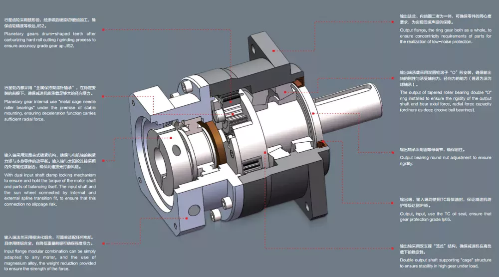
Planetary gearboxes with carrier
A planetary gearbox is a type of gearbox with three or more stages. They have a sun gear, which is usually the input gear, and planet gears, also called the outer gears. The carrier that connects the planet gears to the output shaft is called a ring gear. A planetary gearbox is generally designed to meet specific application and environmental requirements, but there are some factors to consider when choosing one.
The compact footprint of planetary gear sets results in high heat dissipation. This can be a problem in applications with sustained performance or high speeds. As a result, planetary gear sets often include lubricants, which present a cooling effect while also reducing noise and vibration. Some planetary gears even feature a carrier to make the installation process easier. Here are some things to keep in mind when choosing a planetary gear set.
Planetary gearboxes with carrier have several advantages over other types of gearboxes. Unlike conventional gearboxes, planetary gears have a common central shaft, and the tangential forces between the gears cancel out at the center of the ring gear. Because of this, planetary gearboxes are commonly used in input/output applications, and their compact size allows for a wide range of gear reductions. These gears can also produce higher torque density.
Planetary gearboxes with traction
Planetary gears are similar to the planetary system, in that each pinion rotates around a sun gear. The output of the planetary gear unit is lower than the drive rotation speed, but the torque is higher. As the number of planet gear wheels increases, so does the torque. Planetary gear systems contain three to four planet gears, and each is in constant mesh with the others. Power applied to any one member rotates the entire assembly.
Typical applications for planetary gear sets include high-precision motion control. In these applications, high torque, torsional stiffness, and low backlash are required. Planetary gear sets are also ideal for motors with higher speeds. A number of factors contribute to the reliability of these devices. The low backlash and large torque capacity of a planetary gear motor allow them to be used in a wide range of applications.
Planetary gearboxes with electric motors
If you’re in the market for a new gearbox, you may have already heard about planetary gearboxes. The planetary gearbox is a high-efficiency, low-noise gearbox. CZPT manufactures high-torque planetary gearboxes with low backlash. They also make economy planetary gearboxes for lower loads. However, with so many different types available, choosing the right one for your needs can be challenging.
These planetary gearboxes are a compact alternative to conventional pinion-and-gear reducers. They offer high-speed reduction and high torque transfer, and are often used for space-constrained applications. But before you can understand how they work, you’ll need to understand a little about their construction. There are a few things to look for that you may not have noticed before.
The most common type of planetary gearbox is a PM81/LN. It features a set of DC brush motors with diameter 77mm, a stator, and two or more outer gears. Each of these gears is connected to an output shaft through a carrier. They can also be used with brakes, encoders, or a clutch. A planetary gearbox is one of the most reliable gearbox types on the market.
Planetary gearboxes with hydraulic motors
A planetary gearbox is a combination of two gears, the sun and the planets. The sun gear rotates at high speed, while the planets roll around and orbit around the ring gear. The output shaft has the same direction of rotation as the input shaft. The benefits of a planetary gearbox include high reduction ratios, efficiency, space-saving compactness, and higher overload capacity. These gears are also more stable and compact, and they do not suffer from self-locking properties.
Planetary gearboxes are a highly efficient way to power hydraulic lifts. They can be input via electric, hydraulic, or air motors. The drive arrangement can be mounted on a bare shaft, splined shaft, or a parallel keyed input shaft. Depending on the application, bespoke gearboxes can be manufactured with a variety of features and functions.
Planetary gearboxes with combustion engines
There are many different applications of planetary gear sets. The most common is the distribution of power between two wheels in a car’s drive axle. Four-wheel drives use two axle differentials, which are further augmented by a centre differential. Hybrid electric vehicles use summation gearboxes to distribute power from the combustion engine to the wheels and to an electric motor. Planetary gear sets also combine the two different types of motors to form one hybrid vehicle.
To understand how planetary gear sets work, it is important to understand the underlying mechanical principles. For example, Fig. 4.6 shows a stick diagram illustrating two planetary gear sets connected by a lever. The two levers are the same length, so the system is analogous to a single lever. When calculating the torque, it is essential to consider the lever diagram. Similarly, if two gear sets are connected by vertical links, the horizontal links must be horizontal.
editor by czh 2023-02-15
China China OEM 36mm gear box 12v 18v 24v 2800rpm 10rpm low rpm big torque 5nm 60kgf 15 watt electric dc planetary gear reducer motor with Great quality
Guarantee: 3months-1year
Design Amount: TJX36RO
Utilization: Home Appliance, Cosmetic instrument, Sensible Property, Industrial robotic
Variety: Gear MOTOR
Torque: ten N.m
Development: Long lasting Magnet
Commutation: Brush
Protect Function: Drip-evidence
Velocity(RPM): 5~15pcs.* Our guarantee time period is 1 yr.* We have 5 R&D engineers can supply you specialist remedies.* We have a competitive price in Chinese market, or even in the total planet.* ten to 40 days quickly shipping time base on diverse quantities.* We have CE and ROHS certifications.* Our customer support staff will reply to you in twelve hours. Firm Historical past Factory Real Landscape Solution Certificates Consumers Feedback OEM & ODM CAD style: All components of dc gear motor are designed and drawn by our engineers. We use CAXA, NGWN to design and style different gears for our new merchandise. Solidworks is a skilled 3D modeling software, we will design and style motor areas and using 3D model for assembly verification. We have a demanding merchandise advancement process, the standard merchandise improvement cycle in 40-sixty times Packing and shipping 1. All buy schedules are managed separately by every single salesman 2. All resources go via rigid good quality inspection 3. All concluded products will be shipped out after passing inspection 4. All products are packed in foam cartons: The sample delivery time of every expresses are as follows(for example to the US): * DHL 7~12 perform times * FedEx 6~9 function times * TNT 7~12 perform days * UPS 8~eleven work times * EMS ten~18 function days The supply date of bulk items wants distinct negotiation. If the sample is delayed, we will advise you in progress and confirm the new delivery time. FAQ Q: Are you investing business or producer ?A: We are manufacturing unit.Q: How to get?A: Send out us inquiry → Obtain our quotation → Negotiate specifics → Confirm the sample → Indication deal/deposit → Mass manufacturing → Cargo all set → Balance/shipping and delivery → AB60 helical precision Servo Planetary gearbox ratio 3,4,5,6,7,8,10 Even more cooperationQ: How about Sample purchase?A: Sample is available for you. remember to contact us for specifics. As soon as we charge you sample price, please really feel simple, it would be refund when you area formal get.Q: Which shipping and delivery way is accessible?A: DHL, UPS, FedEx, TNT, EMS, China Put up,Sea are obtainable.The other shipping and delivery approaches are also accessible, please speak to us if you require ship by the other delivery way. Q: How extended is the deliver[Producing] and shipping?A: Produce time relies upon on the amount you get. usually it normally takes 7-15 functioning times.Q: My bundle has missing items. What can I do?A: Please speak to our help team and we will confirm your buy with the deal contents.We apologize for any inconveniences. Q: How to verify the payment?A: We take payment by T/T, PayPal, the other payment techniques also could be recognized,Make sure you speak to us just before you shell out by the other payment ways. Also thirty-50% deposit is accessible, the equilibrium money need to be paid just before delivery.
| >>>>>>>>>>>>> Benoy precision computerized planetary gearbox gear reducer for business >Back to Homepage | ||||||||
Planetary Gearbox
This article will explore the design and applications of a planetary gearbox. The reduction ratio of a planetary gearbox is dependent on the number of teeth in the gears. The ratios of planetary gearboxes are usually lower than those of conventional mechanical transmissions, which are mainly used to drive engines and generators. They are often the best choice for heavy-duty applications. The following are some of the advantages of planetary gearboxes.
planetary gearboxes
Planetary gearboxes work on a similar principle to solar systems. They rotate around a center gear called the sun gear, and two or more outer gears, called planet gears, are connected by a carrier. These gears then drive an output shaft. The arrangement of planet gears is similar to that of the Milky Way’s ring of planets. This arrangement produces the best torque density and stiffness for a gearbox.
As a compact alternative to normal pinion-and-gear reducers, planetary gearing offers many advantages. These characteristics make planetary gearing ideal for a variety of applications, including compactness and low weight. The efficiency of planetary gearing is enhanced by the fact that ninety percent of the input energy is transferred to the output. The gearboxes also have low noise and high torque density. Additionally, their design offers better load distribution, which contributes to a longer service life.
Planetary gears require lubrication. Because they have a smaller footprint than conventional gears, they dissipate heat well. In fact, lubrication can even lower vibration and noise. It’s also important to keep the gears properly lubricated to prevent the wear and tear that comes with use. The lubrication in planetary gears also helps keep them operating properly and reduces wear and tear on the gears.
A planetary gearbox uses multiple planetary parts to achieve the reduction goal. Each gear has an output shaft and a sun gear located in the center. The ring gear is fixed to the machine, while the sun gear is attached to a clamping system. The outer gears are connected to the carrier, and each planetary gear is held together by rings. This arrangement allows the planetary gear to be symmetrical with respect to the input shaft.
The gear ratio of a planetary gearbox is defined by the sun gear’s number of teeth. As the sun gear gets smaller, the ratio of the gear will increase. The ratio range of planetary gears ranges from 3:1 to ten to one. Eventually, however, the sun gear becomes too small, and the torque will fall significantly. The higher the ratio, the less torque the gears can transmit. So, planetary gears are often referred to as “planetary” gears.
Their design
The basic design of a Planetary Gearbox is quite simple. It consists of three interconnecting links, each of which has its own torque. The ring gear is fixed to the frame 0 at O, and the other two are fixed to each other at A and B. The ring gear, meanwhile, is attached to the planet arm 3 at O. All three parts are connected by joints. A free-body diagram is shown in Figure 9.
During the development process, the design team will divide the power to each individual planet into its respective power paths. This distribution will be based on the meshing condition of all gears in the system. Then, the design team will proceed to determine the loads on individual gear meshes. Using this method, it is possible to determine the loads on individual gear meshes and the shape of ring gear housing.
Planetary Gearboxes are made of three gear types. The sun gear is the center, which is connected to the other two gears by an internal tooth ring gear. The planet pinions are arranged in a carrier assembly that sets their spacing. The carrier also incorporates an output shaft. The three components in a Planetary Gearbox mesh with each other, and they rotate together as one. Depending on the application, they may rotate at different speeds or at different times.
The planetary gearbox’s design is unique. In a planetary gearbox, the input gear rotates around the central gear, while the outer gears are arranged around the sun gear. In addition, the ring gear holds the structure together. A carrier connects the outer gears to the output shaft. Ultimately, this gear system transmits high torque. This type of gearbox is ideal for high-speed operations.
The basic design of a Planetary Gearbox consists of multiple contacts that must mesh with each other. A single planet has an integer number of teeth, while the ring has a non-integer number. The teeth of the planets must mesh with each other, as well as the sun. The tooth counts, as well as the planet spacing, play a role in the design. A planetary gearbox must have an integer number of teeth to function properly.
Applications
In addition to the above-mentioned applications, planetary gearing is also used in machine tools, plastic machinery, derrick and dock cranes, and material handling equipments. Further, its application is found in dredging equipment, road-making machinery, sugar crystallizers, and mill drives. While its versatility and efficiency makes it a desirable choice for many industries, its complicated structure and construction make it a complex component.
Among the many benefits of using a planetary gearbox, the ability to transmit greater torque into a controlled space makes it a popular choice for many industries. Moreover, adding additional planet gears increases the torque density. This makes planetary gears suitable for applications requiring high torque. They are also used in electric screwdrivers and turbine engines. However, they are not used in everything. Some of the more common applications are discussed below:
One of the most important features of planetary gearboxes is their compact footprint. They are able to transmit torque while at the same time reducing noise and vibration. In addition to this, they are able to achieve a high speed without sacrificing high-quality performance. The compact footprint of these gears also allows them to be used in high-speed applications. In some cases, a planetary gearbox has sliding sections. Some of these sections are lubricated with oil, while others may require a synthetic gel. Despite these unique features, planetary gears have become common in many industries.
Planetary gears are composed of three components. The sun gear is the input gear, whereas the planet gears are the output gears. They are connected by a carrier. The carrier connects the input shaft with the output shaft. A planetary gearbox can be designed for various requirements, and the type you use will depend on the needs of your application. Its design and performance must meet your application’s needs.
The ratios of planetary gears vary depending on the number of planets. The smaller the sun gear, the greater the ratio. When planetary stages are used alone, the ratio range is 3:1 to 10:1. Higher ratios can be obtained by connecting several planetary stages together in the same ring gear. This method is known as a multi-stage gearbox. However, it can only be used in large gearboxes.
Maintenance
The main component of a planetary gearbox is the planetary gear. It requires regular maintenance and cleaning to remain in top shape. Demand for a longer life span protects all other components of the gearbox. This article will discuss the maintenance and cleaning procedures for planetary gears. After reading this article, you should know how to maintain your planetary gearbox properly. Hopefully, you can enjoy a longer life with your gearbox.
Firstly, it is important to know how to properly lubricate a planetary gearbox. The lubricant is essential as gears that operate at high speeds are subject to high levels of heat and friction. The housing of the planetary gearbox should be constructed to allow the heat to dissipate. The recommended oil is synthetic, and it should be filled between 30 and 50 percent. The lubricant should be changed at least every six months or as needed.
While it may seem unnecessary to replace a planetary gearbox, regular servicing will help it last a long time. A regular inspection will identify a problem and the appropriate repairs are needed. Once the planetary gearbox is full, it will plug with gear oil. To avoid this problem, consider getting the unit repaired instead of replacing the gearbox. This can save you a lot of money over a new planetary gearbox.
Proper lubrication is essential for a long life of your planetary gearbox. Oil change frequency should be based on oil temperature and operating speed. Oil at higher temperatures should be changed more frequently because it loses its molecular structure and cannot form a protective film. After this, oil filter maintenance should be performed every few months. Lastly, the gearbox oil needs to be checked regularly and replaced when necessary.
editor by czh 2023-02-13
China Cheap Price Gpg Gpb Box Gearbox Transmission Right Angle Planetary Gear Reducer small planetary gearbox
Product Description
TaiBang Motor Sector Group Co., Ltd.
The primary products is induction motor, reversible motor, DC brush equipment motor, DC brushless gear motor, CH/CV huge gear motors, Planetary gear motor ,Worm gear motor etc, which employed extensively in various fields of producing pipelining, transportation, foodstuff, drugs, printing, material, packing, business office, apparatus, entertainment and so forth, and is the preferred and matched solution for computerized machine.
Design Instruction
GB090-ten-P2
| GB | 090 | 571 | P2 |
| Reducer Series Code | External Diameter | Reduction Ratio | Reducer Backlash |
| GB:Substantial Precision Square Flange Output
GBR:Substantial Precision Appropriate Angle Square Flange Output GE:Higher Precision Spherical Flange Output GER:Substantial Precision Appropriate Round Flange Output |
050:ø50mm 070:ø70mm 090:ø90mm one hundred twenty:ø120mm one hundred fifty five:ø155mm 205:ø205mm 235:ø235mm 042:42x42mm 060:60x60mm 090:90x90mm one hundred fifteen:115x115mm 142:142x142mm a hundred and eighty:180x180mm 220:220x220mm |
571 signifies 1:ten | P0:Higher Precision Backlash
P1:Precision Backlash P2:Regular Backlash |
Main Technological Performance
| Product | Number of stage | Reduction Ratio | GB042 | GB060 | GB060A | GB090 | GB090A | GB115 | GB142 | GB180 | GB220 |
| Rotary Inertia | 1 | three | .03 | .16 | .61 | three.twenty five | 9.21 | 28.ninety eight | 69.61 | ||
| four | .03 | .14 | .48 | 2.74 | seven.54 | 23.sixty seven | 54.37 | ||||
| five | .03 | .13 | .forty seven | 2.seventy one | seven.42 | 23.29 | fifty three.27 | ||||
| 6 | .03 | .13 | .forty five | two.sixty five | 7.25 | 22.seventy five | fifty one.seventy two | ||||
| seven | .03 | .13 | .forty five | two.sixty two | 7.fourteen | 22.48 | 50.ninety seven | ||||
| 8 | .03 | .13 | .44 | two.fifty eight | 7.07 | 22.fifty nine | 50.84 | ||||
| nine | .03 | .13 | .44 | two.fifty seven | 7.04 | 22.fifty three | fifty.sixty three | ||||
| 10 | .03 | .thirteen | .forty four | two.fifty seven | 7.03 | 22.51 | fifty.56 | ||||
| 2 | fifteen | .03 | .03 | .thirteen | .thirteen | .forty seven | .forty seven | 2.71 | seven.42 | 23.29 | |
| twenty | .03 | .03 | .thirteen | .thirteen | .47 | .47 | 2.71 | 7.forty two | 23.29 | ||
| twenty five | .03 | .03 | .13 | .13 | .forty seven | .forty seven | two.seventy one | 7.42 | 23.29 | ||
| 30 | .03 | .03 | .thirteen | .13 | .47 | .47 | 2.71 | seven.forty two | 23.29 | ||
| 35 | .03 | .03 | .thirteen | .13 | .47 | .47 | 2.71 | 7.42 | 23.29 | ||
| forty | .03 | .03 | .13 | .13 | .47 | .47 | two.seventy one | 7.forty two | 23.29 | ||
| 45 | .03 | .03 | .13 | .13 | .forty seven | .forty seven | 2.seventy one | seven.forty two | 23.29 | ||
| 50 | .03 | .03 | .thirteen | .13 | .44 | .44 | two.fifty seven | seven.03 | 22.fifty one | ||
| sixty | .03 | .03 | .13 | .thirteen | .44 | .forty four | 2.fifty seven | seven.03 | 22.51 | ||
| 70 | .03 | .03 | .13 | .thirteen | .forty four | .44 | two.fifty seven | seven.03 | 22.51 | ||
| 80 | .03 | .03 | .thirteen | .13 | .44 | .forty four | two.fifty seven | 7.03 | 22.51 | ||
| ninety | .03 | .03 | .13 | .13 | .forty four | .44 | two.57 | 7.03 | 22.fifty one | ||
| one hundred | .03 | .03 | .13 | .13 | .forty four | .44 | two.fifty seven | seven.03 | 22.51 |
| Item | Amount of phase | GB042 | GB060 | GB060A | GB90 | GB090A | GB115 | GB142 | GB180 | GB220 | |
| Backlash(arcmin) | High Precision P0 | 1 | ≤1 | ≤1 | ≤1 | ≤1 | ≤1 | ≤1 | |||
| 2 | ≤3 | ≤3 | ≤3 | ≤3 | |||||||
| Precision P1 | one | ≤3 | ≤3 | ≤3 | ≤3 | ≤3 | ≤3 | ≤3 | ≤3 | ≤3 | |
| 2 | ≤5 | ≤5 | ≤5 | ≤5 | ≤5 | ≤5 | ≤5 | ≤5 | ≤5 | ||
| Standard P2 | 1 | ≤5 | ≤5 | ≤5 | ≤5 | ≤5 | ≤5 | ≤5 | ≤5 | ≤5 | |
| 2 | ≤7 | ≤7 | ≤7 | ≤7 | ≤7 | ≤7 | ≤7 | ≤7 | ≤7 | ||
| Torsional Rigidity(N.M/arcmin) | 1 | three | 7 | seven | 14 | fourteen | twenty five | 50 | 145 | 225 | |
| two | three | seven | 7 | 14 | fourteen | 25 | 50 | a hundred forty five | 225 | ||
| Noise(dB) | 1,2 | ≤56 | ≤58 | ≤58 | ≤60 | ≤60 | ≤63 | ≤65 | ≤67 | ≤70 | |
| Rated enter pace(rpm) | 1,2 | 5000 | 5000 | 5000 | 4000 | 4000 | 4000 | 3000 | 3000 | 2000 | |
| Max enter velocity(rpm) | one,two | ten thousand | 10000 | ten thousand | 8000 | 8000 | 8000 | 6000 | 6000 | 4000 | |
Noise examination regular:Length 1m,no load.Measured with an enter speed 3000rpm
|
US $50 / Piece | |
1 Piece (Min. Order) |
###
| Application: | Machinery, Agricultural Machinery |
|---|---|
| Function: | Distribution Power, Change Drive Torque, Change Drive Direction, Speed Reduction |
| Layout: | Cycloidal |
| Hardness: | Hardened Tooth Surface |
| Installation: | Vertical Type |
| Step: | Double-Step |
###
| Samples: |
US$ 50/Piece
1 Piece(Min.Order) |
|---|
###
| Customization: |
Available
|
|---|
###
| GB | 090 | 010 | P2 |
| Reducer Series Code | External Diameter | Reduction Ratio | Reducer Backlash |
| GB:High Precision Square Flange Output
GBR:High Precision Right Angle Square Flange Output GE:High Precision Round Flange Output GER:High Precision Right Round Flange Output |
050:ø50mm 070:ø70mm 090:ø90mm 120:ø120mm 155:ø155mm 205:ø205mm 235:ø235mm 042:42x42mm 060:60x60mm 090:90x90mm 115:115x115mm 142:142x142mm 180:180x180mm 220:220x220mm |
010 means 1:10 | P0:High Precision Backlash
P1:Precision Backlash P2:Standard Backlash |
###
| Item | Number of stage | Reduction Ratio | GB042 | GB060 | GB060A | GB090 | GB090A | GB115 | GB142 | GB180 | GB220 |
| Rotary Inertia | 1 | 3 | 0.03 | 0.16 | 0.61 | 3.25 | 9.21 | 28.98 | 69.61 | ||
| 4 | 0.03 | 0.14 | 0.48 | 2.74 | 7.54 | 23.67 | 54.37 | ||||
| 5 | 0.03 | 0.13 | 0.47 | 2.71 | 7.42 | 23.29 | 53.27 | ||||
| 6 | 0.03 | 0.13 | 0.45 | 2.65 | 7.25 | 22.75 | 51.72 | ||||
| 7 | 0.03 | 0.13 | 0.45 | 2.62 | 7.14 | 22.48 | 50.97 | ||||
| 8 | 0.03 | 0.13 | 0.44 | 2.58 | 7.07 | 22.59 | 50.84 | ||||
| 9 | 0.03 | 0.13 | 0.44 | 2.57 | 7.04 | 22.53 | 50.63 | ||||
| 10 | 0.03 | 0.13 | 0.44 | 2.57 | 7.03 | 22.51 | 50.56 | ||||
| 2 | 15 | 0.03 | 0.03 | 0.13 | 0.13 | 0.47 | 0.47 | 2.71 | 7.42 | 23.29 | |
| 20 | 0.03 | 0.03 | 0.13 | 0.13 | 0.47 | 0.47 | 2.71 | 7.42 | 23.29 | ||
| 25 | 0.03 | 0.03 | 0.13 | 0.13 | 0.47 | 0.47 | 2.71 | 7.42 | 23.29 | ||
| 30 | 0.03 | 0.03 | 0.13 | 0.13 | 0.47 | 0.47 | 2.71 | 7.42 | 23.29 | ||
| 35 | 0.03 | 0.03 | 0.13 | 0.13 | 0.47 | 0.47 | 2.71 | 7.42 | 23.29 | ||
| 40 | 0.03 | 0.03 | 0.13 | 0.13 | 0.47 | 0.47 | 2.71 | 7.42 | 23.29 | ||
| 45 | 0.03 | 0.03 | 0.13 | 0.13 | 0.47 | 0.47 | 2.71 | 7.42 | 23.29 | ||
| 50 | 0.03 | 0.03 | 0.13 | 0.13 | 0.44 | 0.44 | 2.57 | 7.03 | 22.51 | ||
| 60 | 0.03 | 0.03 | 0.13 | 0.13 | 0.44 | 0.44 | 2.57 | 7.03 | 22.51 | ||
| 70 | 0.03 | 0.03 | 0.13 | 0.13 | 0.44 | 0.44 | 2.57 | 7.03 | 22.51 | ||
| 80 | 0.03 | 0.03 | 0.13 | 0.13 | 0.44 | 0.44 | 2.57 | 7.03 | 22.51 | ||
| 90 | 0.03 | 0.03 | 0.13 | 0.13 | 0.44 | 0.44 | 2.57 | 7.03 | 22.51 | ||
| 100 | 0.03 | 0.03 | 0.13 | 0.13 | 0.44 | 0.44 | 2.57 | 7.03 | 22.51 |
###
| Item | Number of stage | GB042 | GB060 | GB060A | GB90 | GB090A | GB115 | GB142 | GB180 | GB220 | |
| Backlash(arcmin) | High Precision P0 | 1 | ≤1 | ≤1 | ≤1 | ≤1 | ≤1 | ≤1 | |||
| 2 | ≤3 | ≤3 | ≤3 | ≤3 | |||||||
| Precision P1 | 1 | ≤3 | ≤3 | ≤3 | ≤3 | ≤3 | ≤3 | ≤3 | ≤3 | ≤3 | |
| 2 | ≤5 | ≤5 | ≤5 | ≤5 | ≤5 | ≤5 | ≤5 | ≤5 | ≤5 | ||
| Standard P2 | 1 | ≤5 | ≤5 | ≤5 | ≤5 | ≤5 | ≤5 | ≤5 | ≤5 | ≤5 | |
| 2 | ≤7 | ≤7 | ≤7 | ≤7 | ≤7 | ≤7 | ≤7 | ≤7 | ≤7 | ||
| Torsional Rigidity(N.M/arcmin) | 1 | 3 | 7 | 7 | 14 | 14 | 25 | 50 | 145 | 225 | |
| 2 | 3 | 7 | 7 | 14 | 14 | 25 | 50 | 145 | 225 | ||
| Noise(dB) | 1,2 | ≤56 | ≤58 | ≤58 | ≤60 | ≤60 | ≤63 | ≤65 | ≤67 | ≤70 | |
| Rated input speed(rpm) | 1,2 | 5000 | 5000 | 5000 | 4000 | 4000 | 4000 | 3000 | 3000 | 2000 | |
| Max input speed(rpm) | 1,2 | 10000 | 10000 | 10000 | 8000 | 8000 | 8000 | 6000 | 6000 | 4000 | |
|
US $50 / Piece | |
1 Piece (Min. Order) |
###
| Application: | Machinery, Agricultural Machinery |
|---|---|
| Function: | Distribution Power, Change Drive Torque, Change Drive Direction, Speed Reduction |
| Layout: | Cycloidal |
| Hardness: | Hardened Tooth Surface |
| Installation: | Vertical Type |
| Step: | Double-Step |
###
| Samples: |
US$ 50/Piece
1 Piece(Min.Order) |
|---|
###
| Customization: |
Available
|
|---|
###
| GB | 090 | 010 | P2 |
| Reducer Series Code | External Diameter | Reduction Ratio | Reducer Backlash |
| GB:High Precision Square Flange Output
GBR:High Precision Right Angle Square Flange Output GE:High Precision Round Flange Output GER:High Precision Right Round Flange Output |
050:ø50mm 070:ø70mm 090:ø90mm 120:ø120mm 155:ø155mm 205:ø205mm 235:ø235mm 042:42x42mm 060:60x60mm 090:90x90mm 115:115x115mm 142:142x142mm 180:180x180mm 220:220x220mm |
010 means 1:10 | P0:High Precision Backlash
P1:Precision Backlash P2:Standard Backlash |
###
| Item | Number of stage | Reduction Ratio | GB042 | GB060 | GB060A | GB090 | GB090A | GB115 | GB142 | GB180 | GB220 |
| Rotary Inertia | 1 | 3 | 0.03 | 0.16 | 0.61 | 3.25 | 9.21 | 28.98 | 69.61 | ||
| 4 | 0.03 | 0.14 | 0.48 | 2.74 | 7.54 | 23.67 | 54.37 | ||||
| 5 | 0.03 | 0.13 | 0.47 | 2.71 | 7.42 | 23.29 | 53.27 | ||||
| 6 | 0.03 | 0.13 | 0.45 | 2.65 | 7.25 | 22.75 | 51.72 | ||||
| 7 | 0.03 | 0.13 | 0.45 | 2.62 | 7.14 | 22.48 | 50.97 | ||||
| 8 | 0.03 | 0.13 | 0.44 | 2.58 | 7.07 | 22.59 | 50.84 | ||||
| 9 | 0.03 | 0.13 | 0.44 | 2.57 | 7.04 | 22.53 | 50.63 | ||||
| 10 | 0.03 | 0.13 | 0.44 | 2.57 | 7.03 | 22.51 | 50.56 | ||||
| 2 | 15 | 0.03 | 0.03 | 0.13 | 0.13 | 0.47 | 0.47 | 2.71 | 7.42 | 23.29 | |
| 20 | 0.03 | 0.03 | 0.13 | 0.13 | 0.47 | 0.47 | 2.71 | 7.42 | 23.29 | ||
| 25 | 0.03 | 0.03 | 0.13 | 0.13 | 0.47 | 0.47 | 2.71 | 7.42 | 23.29 | ||
| 30 | 0.03 | 0.03 | 0.13 | 0.13 | 0.47 | 0.47 | 2.71 | 7.42 | 23.29 | ||
| 35 | 0.03 | 0.03 | 0.13 | 0.13 | 0.47 | 0.47 | 2.71 | 7.42 | 23.29 | ||
| 40 | 0.03 | 0.03 | 0.13 | 0.13 | 0.47 | 0.47 | 2.71 | 7.42 | 23.29 | ||
| 45 | 0.03 | 0.03 | 0.13 | 0.13 | 0.47 | 0.47 | 2.71 | 7.42 | 23.29 | ||
| 50 | 0.03 | 0.03 | 0.13 | 0.13 | 0.44 | 0.44 | 2.57 | 7.03 | 22.51 | ||
| 60 | 0.03 | 0.03 | 0.13 | 0.13 | 0.44 | 0.44 | 2.57 | 7.03 | 22.51 | ||
| 70 | 0.03 | 0.03 | 0.13 | 0.13 | 0.44 | 0.44 | 2.57 | 7.03 | 22.51 | ||
| 80 | 0.03 | 0.03 | 0.13 | 0.13 | 0.44 | 0.44 | 2.57 | 7.03 | 22.51 | ||
| 90 | 0.03 | 0.03 | 0.13 | 0.13 | 0.44 | 0.44 | 2.57 | 7.03 | 22.51 | ||
| 100 | 0.03 | 0.03 | 0.13 | 0.13 | 0.44 | 0.44 | 2.57 | 7.03 | 22.51 |
###
| Item | Number of stage | GB042 | GB060 | GB060A | GB90 | GB090A | GB115 | GB142 | GB180 | GB220 | |
| Backlash(arcmin) | High Precision P0 | 1 | ≤1 | ≤1 | ≤1 | ≤1 | ≤1 | ≤1 | |||
| 2 | ≤3 | ≤3 | ≤3 | ≤3 | |||||||
| Precision P1 | 1 | ≤3 | ≤3 | ≤3 | ≤3 | ≤3 | ≤3 | ≤3 | ≤3 | ≤3 | |
| 2 | ≤5 | ≤5 | ≤5 | ≤5 | ≤5 | ≤5 | ≤5 | ≤5 | ≤5 | ||
| Standard P2 | 1 | ≤5 | ≤5 | ≤5 | ≤5 | ≤5 | ≤5 | ≤5 | ≤5 | ≤5 | |
| 2 | ≤7 | ≤7 | ≤7 | ≤7 | ≤7 | ≤7 | ≤7 | ≤7 | ≤7 | ||
| Torsional Rigidity(N.M/arcmin) | 1 | 3 | 7 | 7 | 14 | 14 | 25 | 50 | 145 | 225 | |
| 2 | 3 | 7 | 7 | 14 | 14 | 25 | 50 | 145 | 225 | ||
| Noise(dB) | 1,2 | ≤56 | ≤58 | ≤58 | ≤60 | ≤60 | ≤63 | ≤65 | ≤67 | ≤70 | |
| Rated input speed(rpm) | 1,2 | 5000 | 5000 | 5000 | 4000 | 4000 | 4000 | 3000 | 3000 | 2000 | |
| Max input speed(rpm) | 1,2 | 10000 | 10000 | 10000 | 8000 | 8000 | 8000 | 6000 | 6000 | 4000 | |
Planetary Gearbox Advantages and Disadvantages
A planetary gearbox is a type of mechanical drive with a single output shaft. They are suitable for both clockwise and counterclockwise rotations, have less inertia, and operate at higher speeds. Here are some advantages and disadvantages of this type of gearbox. Let us see what these advantages are and why you should use them in your applications. Listed below are some of the benefits of planetary gearboxes.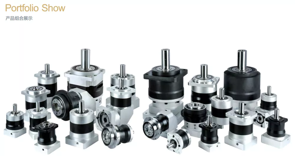
Suitable for counterclockwise and clockwise rotation
If you want to teach children about the clock hands, you can buy some resources for counterclockwise and asymmetrical rotation. These resources include worksheets for identifying degrees of rotation, writing rules for rotation, and visual processing. You can also use these resources to teach angles. For example, the translation of shapes activity pack helps children learn about the rotation of geometric shapes. Similarly, the visual perception activity sheet helps children understand how to process information visually.
Various studies have been done to understand the anatomical substrate of rotations. In a recent study, CZPT et al. compared the position of the transitional zone electrocardiographically and anatomically. The authors found that the transitional zone was normal in nine of 33 subjects, indicating that rotation is not a sign of disease. Similarly, a counterclockwise rotation may be caused by a genetic or environmental factor.
The core tip data should be designed to work in both clockwise and counterclockwise rotation. Counterclockwise rotation requires a different starting point than a clockwise rotation. In North America, star-delta starting is used. In both cases, the figure is rotated about its point. Counterclockwise rotation, on the other hand, is done in the opposite direction. In addition, it is possible to create counterclockwise rotation using the same gimbal.
Despite its name, both clockwise and counterclockwise rotation requires a certain amount of force to rotate. When rotating clockwise, the object faces upwards. Counterclockwise rotation, on the other hand, starts from the top position and heads to the right. If rotating in the opposite direction, the object turns counterclockwise, and vice versa. The clockwise movement, in contrast, is the reverse of counterclockwise rotation.
Has less inertia
The primary difference between a planetary gearbox and a normal pinion-and-gear reducer is the ratio. A planetary gearbox will produce less inertia, which is an important advantage because it will reduce torque and energy requirements. The ratio of the planetary gearbox to its fixed axis counterpart is a factor of three. A planetary gearbox has smaller gears than a conventional planetary, so its inertia is proportional to the number of planets.
Planetary gears are less inertia than spur gears, and they share the load across multiple gear teeth. This means that they will have low backlash, and this is essential for applications with high start-stop cycles and frequent rotational direction changes. Another benefit is the high stiffness. A planetary gearbox will have less backlash than a spur gearbox, which means that it will be more reliable.
A planetary gearbox can use either spur or helical gears. The former provides higher torque ratings while the latter has less noise and stiffness. Both types of gears are useful in motorsports, aerospace, truck transmissions, and power generation units. They require more assembly time than a conventional parallel shaft gear, but the PD series is the more efficient alternative. PD series planetary gears are suitable for many applications, including servo and robotics.
In contrast, a planetary gear set can have varying input speed. This can affect the frequency response of the gearset. A mathematical model of the two-stage planetary gears has non-stationary effects and correlates with experimental findings. Fig. 6.3 shows an addendum. The dedendum’s minimum value is approximately 1.25m. When the dedendum is at its smallest, the dedendum has less inertia.
Offers greater reliability
The Planetary Gearbox is a better option for driving a vehicle than a standard spur gearbox. A planetary gearbox is less expensive, and they have better backlash, higher load capacity, and greater shock loads. Unlike spur gearboxes, however, mechanical noise is virtually nonexistent. This makes them more reliable in high-shock situations, as well as in a wide range of applications.
The Economy Series has the same power density and torque capacity of the Precision Helical Series, but it lacks the precision of the latter. In contrast, Economy Series planetary gearboxes feature straight spur planetary gearing, and they are used in applications requiring high torque. Both types of gearboxes are compatible with NEMA servo motors. If torque density is important, a planetary gearbox is the best choice.
The Dispersion of External Load: The SSI model has been extensively used to model the reliability of planetary gear systems. This model takes the contact force and fatigue strength of the system as generalized stress and strength. It also provides a theoretical framework to evaluate the reliability of planetary gear systems. It also has many other advantages that make it the preferred choice for high-stress applications. The Planetary Gearbox offers greater reliability and efficiency than traditional rack and pinion gear systems.
Planetary gearing has greater reliability and compact design. Its compact design allows for wider applications with concerns about space and weight. Additionally, the increased torque and reduction makes planetary gearboxes an excellent choice for a wide variety of applications. There are three major types of planetary gearboxes, each with its own advantages. This article describes a few of them. Once you understand their workings, you will be able to choose the best planetary gearbox for your needs.
Has higher operating speeds
When you look at planetary gearboxes, you might be confused about which one to choose. The primary issue is the application of the gearbox. You must also decide on secondary factors like noise level, corrosion resistance, construction, price, and availability worldwide. Some constructors work faster than others and deliver the gearboxes on the same day. However, the latter ones often deliver the planetary gearbox out of stock.
Compared to conventional gearboxes, a planetary gearbox can run at higher speeds when the input speed fluctuates. However, these gears are not very efficient in high-speed applications because of their increased noise levels. This makes planetary gears unsuitable for applications involving a great deal of noise. That is why most planetary gears are used in small-scale applications. There are some exceptions, but in general, a planetary gearbox is better suited for applications with higher operating speeds.
The basic planetary gearbox is a compact alternative to normal pinion-and-gear reducers. They can be used in a wide variety of applications where space and weight are concerns. Its efficiency is also higher, delivering 97% of the power input. It comes in three different types based on the performance. A planetary gearbox can also be classified as a worm gear, a spur gear, or a sprocket.
A planetary gearhead has a high-precision design and can generate substantial torque for their size. It also reduces backlash to two arc-min. Additionally, it is lubricated for life, which means no maintenance is needed. It can fit into a small machine envelope and has a small footprint. Moreover, the helical crowned gearing provides fast positioning. A sealed gearbox prevents abrasive dust from getting into the planetary gearhead.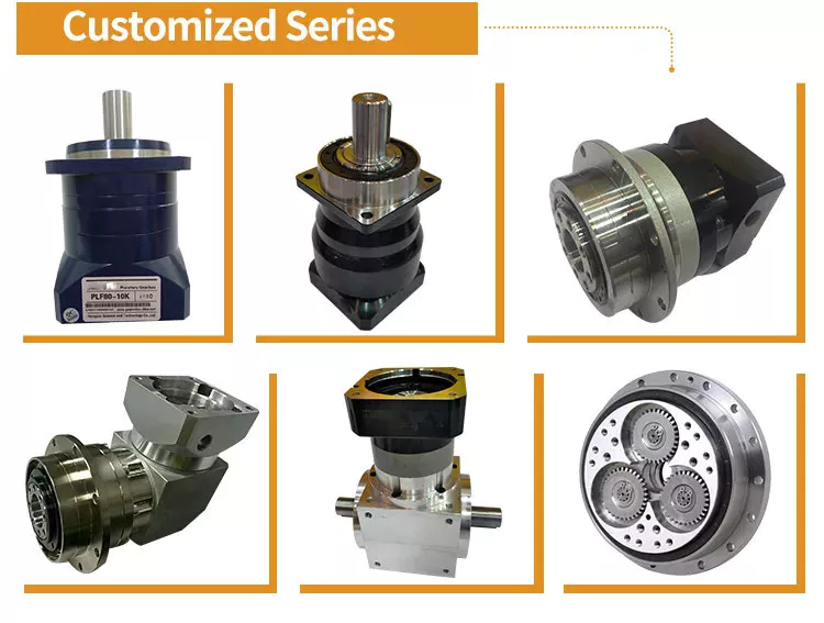
Has drawbacks
The design of a planetary gearbox is compact and enables high torque and load capability in a small space. This gear arrangement also reduces the possibility of wear and tear. Planet gears are arranged in a planetary fashion, allowing gears to shift under load and a uniform distribution of torque. However, some disadvantages of planetary gears must be considered before investing in this gearbox.
While the planetary gearbox is a high precision motion-control device, its design and maintenance requirements are a concern. The bearing load is high, requiring frequent lubrication. Also, they are inaccessible. Despite these drawbacks, planetary gearboxes are suitable for a variety of tasks. They also have low backlash and high torsional stiffness, making them excellent choices for many applications.
As a result, the speed of a planetary gearbox varies with load and speed. At lower ratios, the sun gear becomes too large in relation to the planet gears. As the ratio increases, the sun gear will become too low, reducing torque. The planetary gears also reduce their torque in high-speed environments. Consequently, the ratio is a crucial consideration for planetary gearbox condition monitoring.
Excess drag may result from out-of-tolerance components or excessive lubrication. Drag should be measured both in directions and be within acceptable ranges. Grease and oil lubrication are two common planetary gearbox lubricants, but the choice is largely dependent on your application. While grease lubricates planetary gears well, oil needs maintenance and re-lubrication every few thousand hours.
editor by czh 2022-12-24